13
CONTROLS
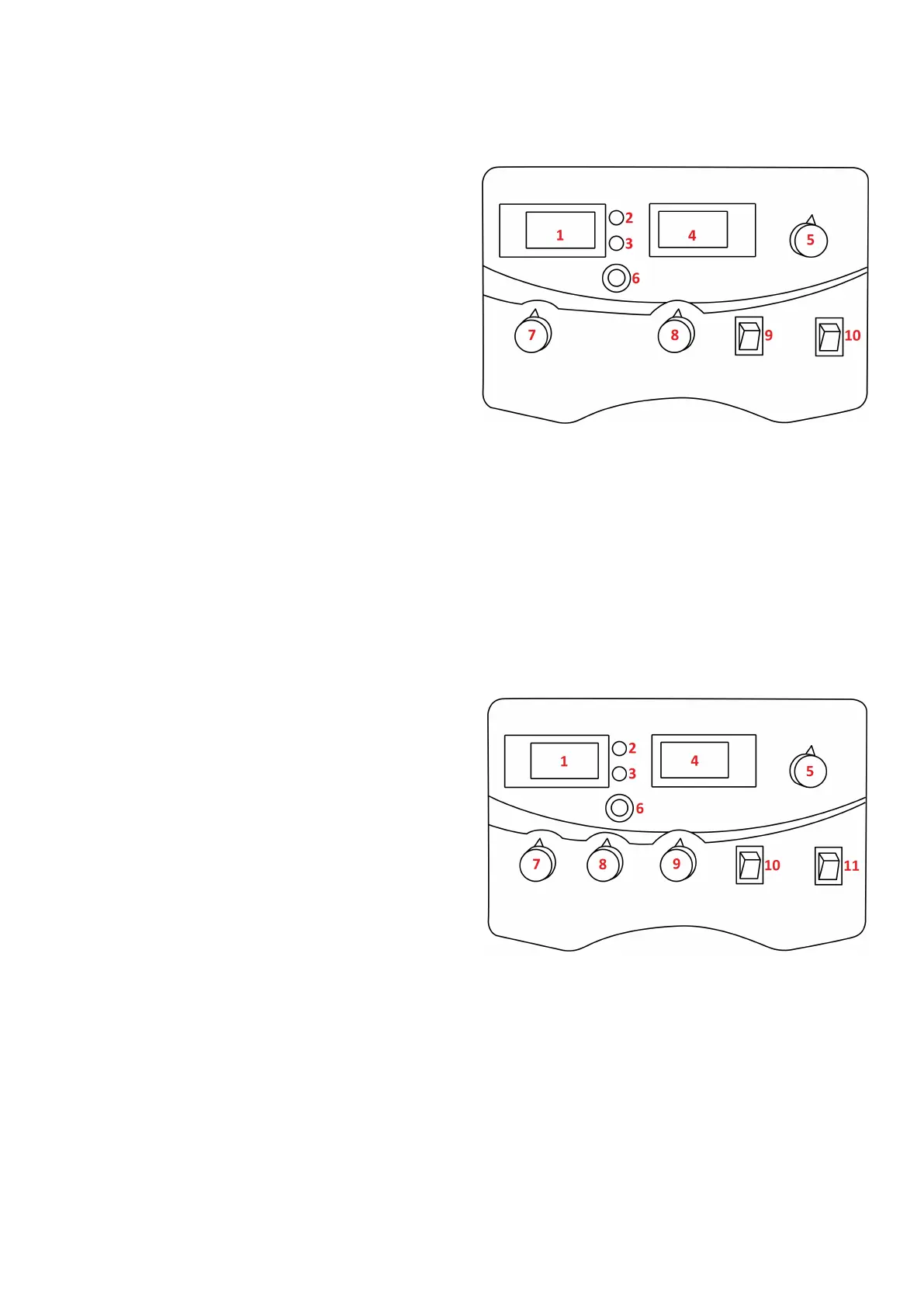
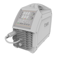
Front control panel view Jasic MIG 202C and 252C
1. Digital voltmeter: Displays welding voltage
2. Power LED: Indicates that power is present to the
machine and that the power switch of the machine
is turned on
3. Overheang LED: Indicates overheang, when this
LED is on it indicates that the temperature inside
the machine is too high and the machine is under
overheang protecon status
4. Digital ammeter: Displays preset and actual amps
5. Current control dial: The amperage dial used with
MMA only and adjusts the amount of welding
current delivered by the power source
6. Wire inch buon: Pressing this buon acvates the feed motor which in turn pushes the welding wire
through the MIG torch and p
7. Voltage control dial: Used in MIG mode only, this dial increases or decreases the output voltage to
assist in nding the opmum voltage level required dependent on the wire feed, wire size and
applicaon being undertaken (see set up chart on page 29)
8. Wire feed speed control: The rate of speed (metres per minute) at which the ller metal is fed and
consumed in the weld, which in turn adjusts the output current by varying the amount of MIG wire
delivered to the welding arc (see set up chart on page 29)
9. Mode selector switch: To switch between MIG and MMA welding modes
10. MIG mode selecon switch: Standard MIG gun/spool gun selector
Front control panel view Jasic MIG 352C
1. Digital voltmeter: Displays welding voltage
2. Power LED: Indicates that power is present to the
machine and that the power switch of the machine
is turned on
3. Overheang LED: Indicates overheang, when this
LED is on it indicates that the temperature inside
the machine is too high and the machine is under
overheang protecon status
4. Digital ammeter: Displays preset and actual amps
5. Current control dial: The amperage dial used with
MMA only and adjusts the amount of welding
current delivered by the power source
6. Wire inch buon: Pressing this buon acvates the feed motor which in turn pushes the welding wire
through the MIG torch and p
7. Voltage control dial: Used in MIG mode only, this dial increases or decreases the output voltage to
assist in nding the opmum voltage level required dependent on the wire feed, wire size and
applicaon being undertaken (see set up chart on page 29)
8. Wire feed speed control: The rate of speed (metres per minute) at which the ller metal is fed and
consumed in the weld, which in turn adjusts the output current by varying the amount of MIG wire
delivered to the welding arc (see set up chart on page 29)
9. Inductor control: A variable inductance control to give the operator a more precise output in MIG
10. Mode selector switch: To switch between MIG, MMA and TIG welding modes
11. MIG mode selecon switch: Standard MIG gun/spool gun selector