JasperMIDI guide
Construction
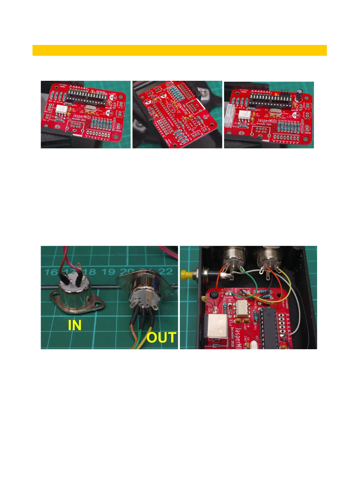
It is a fairly quick build. Solder the PCB as normal. Start with the smaller components – resistors
etc. and moving onto the taller items – IC sockets, voltage regulator, and the electrolytic capacitors.
Take care to get the polarity of the diodes, LED and electrolytic capacitors correct. For the LED and
electrolytic capacitors the longer (+ve) leg goes into the square shaped pad. Also the negative side
of the electrolytic capacitors are shaded on the PCB silk-screen. Before installing the ICs, connect
power to the PCB and check that you are getting 5V at the correct places.
Push button: Connect the push-button to the pads marked A0 and GND. This allows setting the
MIDI channel number. It is MIDI channel 1 by default, so leave the push-button out if you are happy
with this and don’t anticipate changing it.
MIDI DIN Socket wiring: cut your wire long enough to reach from the JasperMIDI PCB headers to
where the sockets are located in your enclosure.
LED: The LED can be soldered directly to the PCB if you’re making an external box, or it can have
wires soldered to its pins so it can be positioned away from the PCB. A standard 2.54mm (0.1")
pitch MTA100/MolexKK or JST XH header can be soldered into the LED position on the PCB.
v1 Page 4 of 9 November 2017