JasperMIDI guide
Installing in a Jasper enclosure
If you built Jasper with a case including a speaker, then there will be enough room to install
JasperMIDI. You can omit soldering the mini-din socket, and the power regulator components. Use
hookup wire or ribbon cable to connect JasperMIDI to the Jasper main board. Use the 5V header
on the JasperMIDI PCB to the 5V pads (or connector) on the Link2 header. When connecting the
link port, make sure the wires are correctly connected. It’s a good idea to use coloured wire and
use a continuity tester so they don’t get mixed up.
The pin marked ‘G’ on the Link port header is a connection to GND, and can be omitted if you
connect 5V and GND to the 5V In header.
Remember to allow enough space in your enclosure for fitting the PCB and panel mounted
sockets, switch and LED.
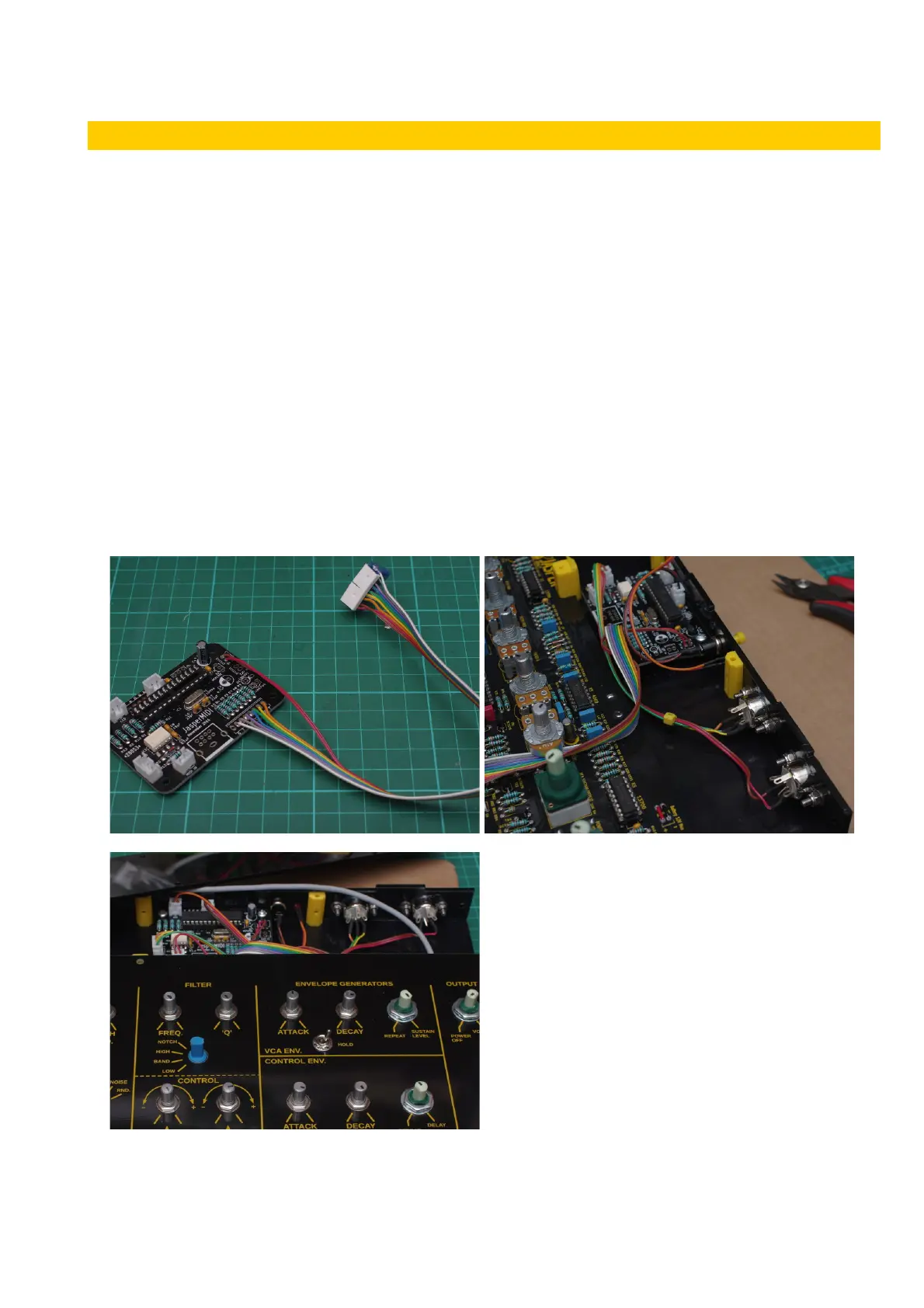
The images below shows JasperMIDI installed behind the main Jasper PCB in an acrylic case. The
DIN sockets, LED, push button are connected using ribbon cable to JST crimp connectors on the
MIDI PCB. The Link port and 5V In connections are soldered on the PCB, but are terminated with
MTA100 plugs that connect to the Link2 header on the main PCB. Allow enough length on the
ribbon cable to reach the header.
v1 Page 5 of 9 November 2017