Instruction Manual FS140 and FS100 - 6115... / 6116...
© BA_FS140+100_EN_Rev02-2010.doc Page 5 of 20
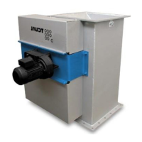
4.1.1 Manually actuated slide valves
Before installation, check whether the slide valve is adjusted correctly. Adjust the setting if necessary:
Check whether the slide valve closes tightly.
Inductive limit switches (optional): check the settings “Slide OPEN” - “Slide CLOSED”.
See section 4.1.3 for information about setting the limit switches.
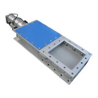
4.1.2 Pneumatically actuated slide valves
Before a pneumatically actuated slide valve is installed, a check should be made to see that it is working
properly:
Connect the cylinder
Connect the limit switches to the control system
Choose the pneumatic setting “CLOSED” (“ZU”)
The tip of the slide plate may be no further than 5 mm away from the frame
If necessary, the limit switches must be set:
Undo the lock nuts and screw the limit switches in or out until the correct end position has been
reached.
Caution! Damage to property!
Caution: Do not screw the limit switches in too far, otherwise the switching lug will
shear them off.
Caution! Danger of injury!
Caution: Look out for shear point when closing the slide valve.
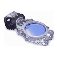
4.1.3 Motor-actuated slide valves
Before a motor-actuated slide valve is installed, a check should be made to see that it is working properly.
Connect the motor - if using AUMA motors it may be necessary to connect a torque monitor.
Consult the drive manufacturer’s operating instructions!
Connect the limit switches to the control system
Choose the electrical setting “CLOSED” (“ZU”)
The tip of the slide plate may be no further than 5 mm away from the frame
If necessary, the limit switches must be set:
Undo the lock nuts and screw the limit switches in or out until the correct end position has been
reached.
Caution! Damage to property!
Caution: Do not screw the limit switches in too far, otherwise the switching lug will
shear them off.
Caution! Danger of injury!
Caution: Look out for shear point when closing the slide valve.
 Loading...