61
Slideout SyStemS
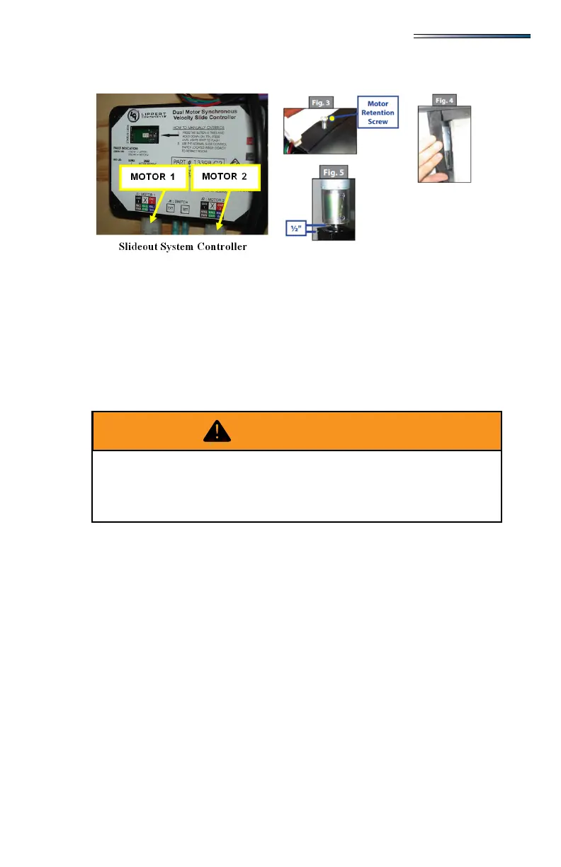
5. When the room is completely in, plug both motor connectors back into the control
module. This will apply the motor brakes for road travel.
Disengage motors, manually retract the room and travel lock
6. Locate and remove the motor retention screw which can be found near the top of each
vertical column (Fig. 3).
7. Bend back the wipe seal and visually locate the motor (Fig. 4).
8. Pull the motor up until it disengages (about 1/2 inch).
9. Repeat this process for both sides of the slide room.
10. Physically push or pull the room back into the opening, keep both sides relatively even.
11. The room must be travel locked to keep the room in place for road travel.
Error Codes
When an error code occurs during operation, the board will use the LEDs lights to indicate
where the problem is. For motor specic faults the green LED will blink (1) time for motor
#1 and (2) times for motor #2. The red LED will blink from 2 to 9 times depending on the
error code:
Error codes are as follows:
2 times Battery drop out: battery capacity low enough to drop below 6 volts while
running.
3 times Low battery: voltage is below 8 volts at the start of a cycle.
4 times High battery: voltage is greater than 18 volts.
5 times Excessive motor current: high amperage, also indicated by (1) side of the slide
continually stalling.
6 times Motor short circuit: motor or wiring to motor has shorted out.
8 times Hall signal not present: encoder is not providing a signal; usually a wiring
problem.
9 times Hall power short to ground: power to encoder has been shorted to ground;
usually a wiring problem.
DO NOT MOVE THE RV UNLESS THE MOTORS ARE PLUGGED IN
TO THE CONTROLLER AND THERE IS BATTERY POWER TO THE
RV. THIS SETS THE BRAKES ON THE SLIDEOUTS TO PREVENT
THEM FROM MOVING DURING TRANSIT.