SECTION 5 - SLIDEOUT SYSTEMS CLASS C MOTOR HOMES
5 - 2
OPERATING THE SLIDEOUT
1. The auxiliary battery (customer supplied) must be fully charged and
connected. If possible, the RV should be hooked up to 120-volt AC power so
the converter operates.
2. The RV must be level and the stabilizer jacks in the extended
position.
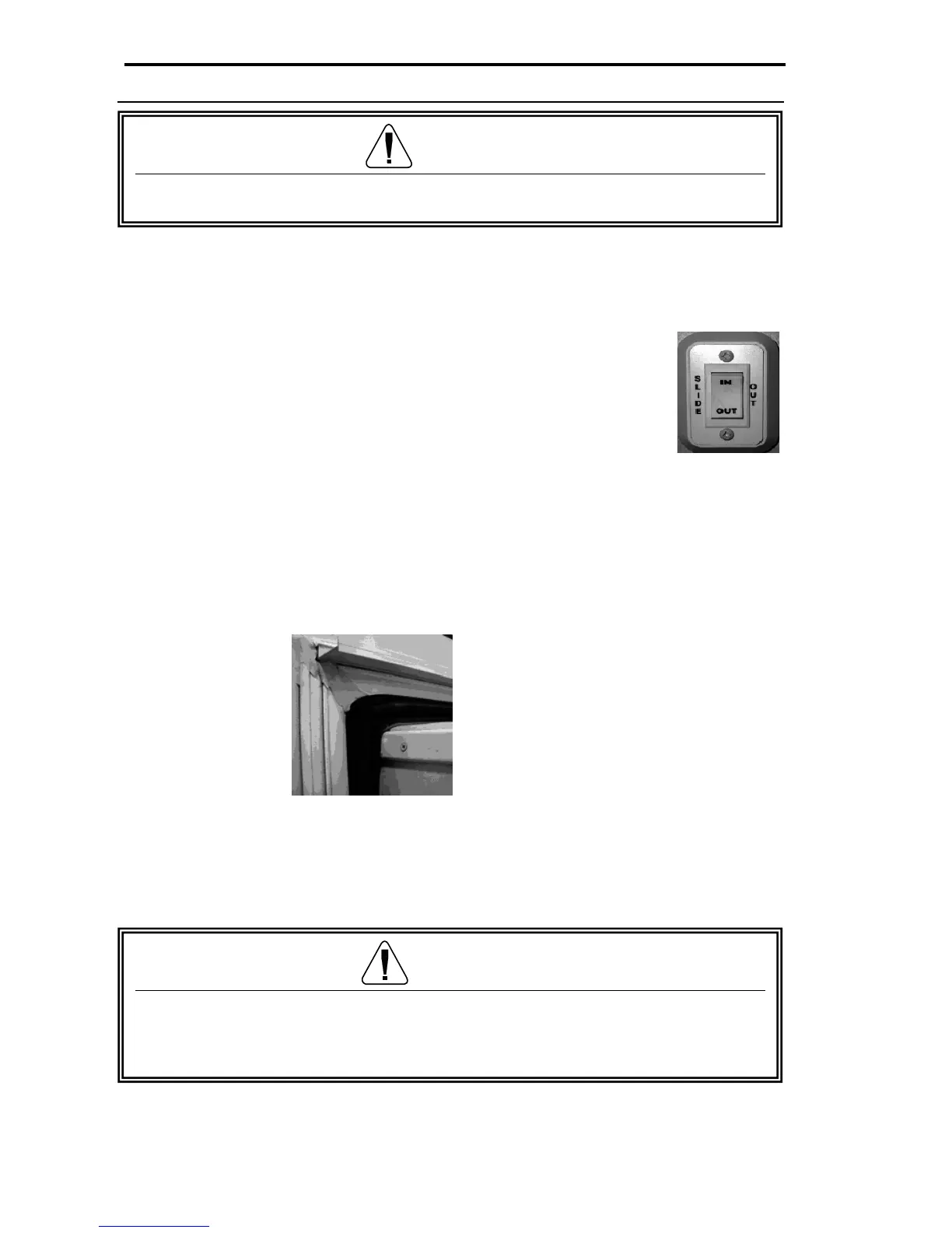
3. Locate the slideout room control switch. The main slideout
switch is located in the command center. The bedroom
slideout switch may be located in the command center or on
a bedroom interior wall depending on the model.
4. To move the room out, press the OUT section of the switch
and hold it until the motor stops (travel time is approx. 25
seconds). Operating the switch after the room is fully
extended will damage the switch and motor.
After the slideout is extended, verify that the corners of the black
rubber seal are set up correctly. The corners of this seal are cut at a 45° angle.
The top of the seal must overlap the side of the seal to avoid the possibility of
water penetration.
Retracting slideout room
Press the IN section of the slideout control switch and hold it until the motor stops.
Operating the switch after the room is fully retracted will damage the switch and
motor.
Maintenance
Fig. 5.3
Bedroom
slideout
control
switch
Fig. 5.4 Exterior
slideout room corner
CAUTION
Additional support jacks are not needed under the slideout. Damage can
occur to
acks.
WARNING
Do not work on your system unless the 12-volt DC (auxiliary battery, customer
supplied) and 120-volt AC electrical systems (shore line power cord) have
been disconnected.