AX700 4
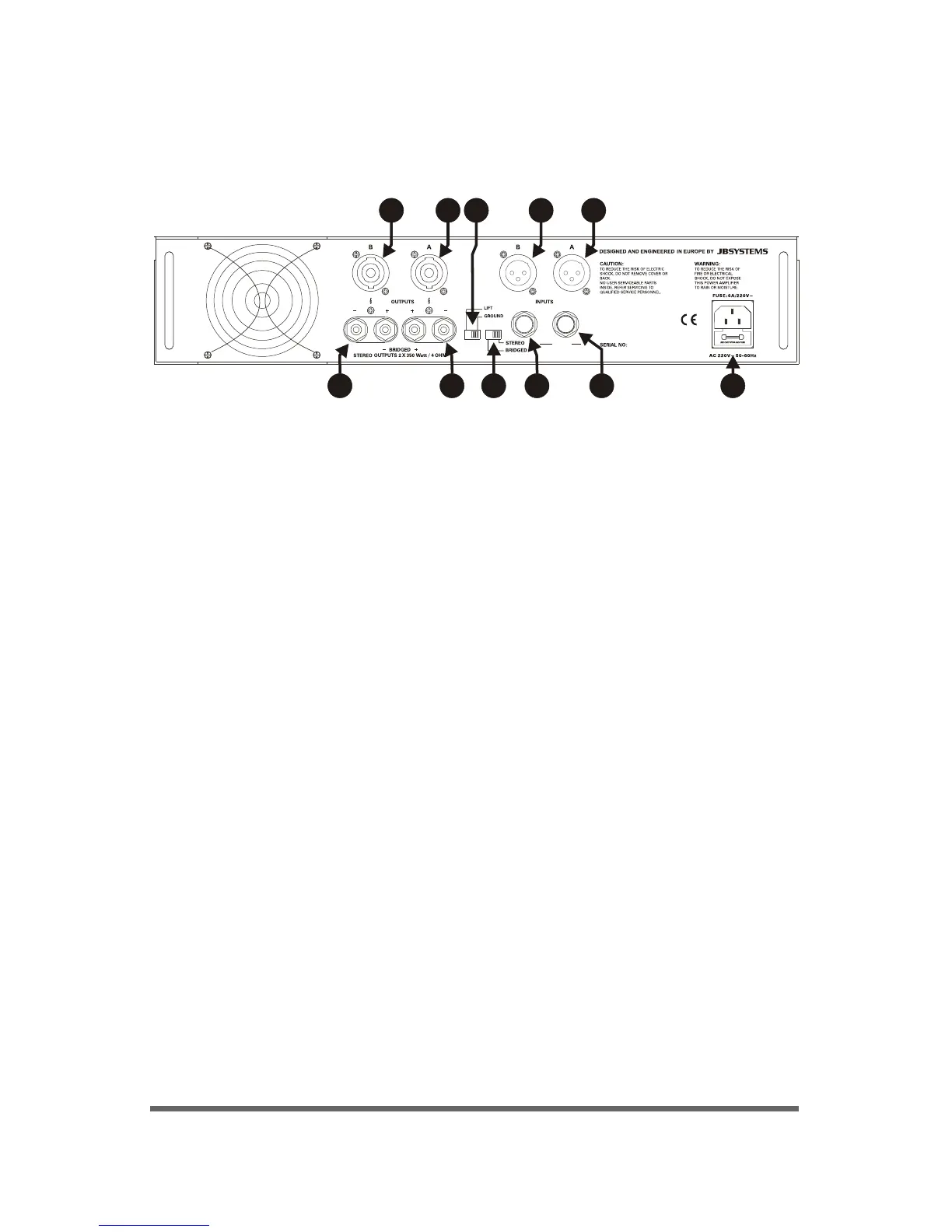
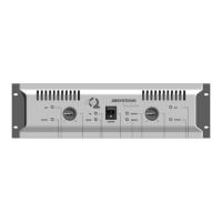
REAR PANEL
7. Mode Selector: two modes to select:
A. Stereo Mode
B. Bridge Mode (CH1 working): output voltage double
1. Standard Power Connector (Fuse Socket):
Attention: use the correct fuse when changed.
2.
3.
CH1/CH2 Output Connector: Use Speakon connector
CH1/CH2 Output Connector: Use Binding post connector
4. Ground Lift Switch.
5.
6.
CH1/CH2 Input Connector: Use a 1/4” connector
CH1/CH2 Input Connector: Use an XLR connector
3 3 5 57 1
2 6 642
STEREO OUTPUT SPEAKON:
(PIN1+/PIN2+)+, (PIN1-/PIN2-)-
BRIDGE OUTPUT SPEAKON:
A(PIN1+/PIN2+)+, B(PIN1+/PIN2+)-
OUTPUT WIRING:
JACK:
TIP: +
RING: -
SLEEVE: GND
XLR:
PIN1: GND
PIN2: +
PIN3: -