The JBL 4400A Series Studio Monitors are high-quality compact monitors designed for professional audio applications, specifically tailored for the musical needs of the 1990s and beyond. These monitors prioritize maximum sonic accuracy through balanced frequency response, low distortion characteristics, and controlled off-axis response, aiming to reduce listener fatigue compared to other monitors.
Function Description:
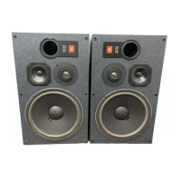
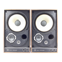
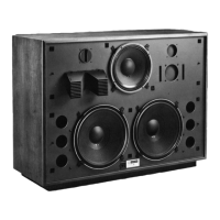
The 4400A Series monitors serve as critical listening tools in studio environments, providing an accurate and uncolored reproduction of audio. They are designed for close-proximity monitoring, typically positioned atop or just behind a mixing console's meter bridge. The series includes mirror-imaged systems, meaning there are designated "Left" and "Right" units, which are crucial for achieving optimal stereo imaging and a symmetrical wavefront. The design incorporates insights from numerous recording and mixing engineers, ensuring their performance meets the demands of professional audio production for music, television, and movie soundtracks.
Important Technical Specifications:
4408A Model:
- Frequency Range (-10 dB): 35 Hz - 30 kHz
- Frequency Response (±2 dB): 50 Hz - 20 kHz
- Power Rating: 100 watts, pink noise
- Sensitivity: 89 dB SPL, 2.83 V @ 1 meter
- Nominal Impedance: 8 ohms
- Crossover Frequency: 2.5 kHz
- Transducer Complement: 200 mm (8 in) LF Felted Cone, 25 mm (1 in) HF Pure Titanium Dome
- Dimensions (H x W x D): 438 x 305 x 293 mm (17 1/4 x 12 x 11 5/8 in)
- Weight (each): 12 kg (26 lbs)
- Finish: Matte Gray Laminate
- Grille Color: Charcoal
4410A Model:
- Frequency Range (-10 dB): 33 Hz - 30 kHz
- Frequency Response (±2 dB): 45 Hz - 20 kHz
- Power Rating: 125 watts, pink noise
- Sensitivity: 90 dB SPL, 2.83 V @ 1 meter
- Nominal Impedance: 8 ohms
- Crossover Frequency: 900 Hz, 4.0 kHz
- Transducer Complement: 250 mm (10 in) LF Aquaplas, 125 mm (5 in) Midrange Cone, 25 mm (1 in) HF Pure Titanium Dome
- Dimensions (H x W x D): 597 x 362 x 286 mm (23 1/2 x 14 1/4 x 11 1/4 in)
- Weight (each): 19 kg (43 lbs)
- Finish: Matte Gray Laminate
- Grille Color: Charcoal
4412A Model:
- Frequency Range (-10 dB): 30 Hz - 30 kHz
- Frequency Response (±2 dB): 45 Hz - 20 kHz
- Power Rating: 150 watts, pink noise
- Sensitivity: 89 dB SPL, 2.83 V @ 1 meter
- Nominal Impedance: 8 ohms
- Crossover Frequency: 850 Hz, 4.0 kHz
- Transducer Complement: 300 mm (12 in) LF Aquaplas, 125 mm (5 in) Midrange Cone, 25 mm (1 in) HF Pure Titanium Dome
- Dimensions (H x W x D): 362 x 597 x 286 mm (14 1/4 x 23 1/2 x 11 1/4 in)
- Weight (each): 21 kg (47 lbs)
- Finish: Matte Gray Laminate
- Grille Color: Charcoal
Usage Features:
-
Placement:
- Listening Distance: Ideal placement is 1 to 1.5 meters (3-5 ft) from the listening position, typically over the meter bridge or on stands. This range provides greater control over listening room interaction.
- Vertical vs. Horizontal Orientation: Models 4408A and 4410A are engineered for vertical positioning, though the 4408A can be used horizontally with minimal performance impact. The 4412A is designed for horizontal positioning.
- Angling Towards the Listening Area: Monitors should be angled directly towards the listener, with the center of the high-frequency transducer aligned with the listener's eye level.
- Placement Near Walls: While best frequency response is achieved away from walls, the monitors can be used in home studios or video post-production centers where placement near walls or corners is unavoidable.
- Mirror-Imaging: As mirror-imaged pairs, the high-frequency elements should generally be located on the outside edge of the enclosure to form an equilateral triangle with the listener. If space restrictions force speakers farther apart, locating the high-frequency elements to the inside may improve imaging.
- Stray Magnetic Fields: Due to powerful magnets, these monitors can generate stray magnetic fields that may affect video monitors, computers, or other magnetically sensitive equipment. It's recommended to place them no closer than 450 mm (18 inches) to such equipment. JBL offers Control Series or 4200 Series monitors for magnetically shielded options.
-
Connection:
- Equipped with 5-way binding post input connectors.
- Positive voltage to the "Red" (+) terminal causes forward motion in the low-frequency cone.
- Connectors accept up to 12 AWG bare wire, Spade Lugs, or a standard Banana jack.
- The spacing of the input terminals allows for a standard Dual Banana jack.
- Use two-conductor insulated speaker wire, preferably 16 AWG or heavier. For cable runs exceeding 10 meters (30 ft), use 14 or 12 AWG wire.
-
Power Requirements:
- JBL recommends that the power amplifier's output rating be no less than the rated maximum power handling of the loudspeaker system.
- A common misconception is that a lower-powered amplifier cannot damage a loudspeaker. In fact, the highest percentage of component failures occur when an amplifier cannot deliver clean, undistorted power, leading to clipping and damage.
Maintenance Features:
-
Component Repair/Replacement:
- In case of component failure, it is recommended to take the defective system to an authorized JBL Service Center. Contact JBL Professional for the nearest repair center.
- If no authorized service centers are nearby, it may be necessary to ship the defective component separately to prevent freight damage to the enclosure.
-
Removing the Low Frequency Transducer:
- Lay the enclosure on its back.
- Carefully pull the grille away from the baffle (lifting each corner a little at a time if tight).
- Remove the four screws holding the LF transducer in place.
- Lift the component out of the baffle and disconnect the leads from the terminals.
- Package the component carefully for shipping.
-
Removing the Midrange and High Frequency Dome:
- These transducers are held in place with four screws.
- Once screws are removed, they should lift out easily. If they appear "glued" due to painted surfaces or pressure, use a sharp-edged tool (e.g., a knife) to gently lift the edge of the mounting flange away from the enclosure.
-
Reconnecting Repaired or Replacement Components:
- The crossover networks use a specific color code to ensure correct hook-up:
- Green = LF Positive (+)/Red
- Green/Black = LF Negative (-)/Black
- White = MF Positive (+)/Red
- White/Black = MF Negative (-)/Black
- Yellow = HF Positive (+)/Red
- Yellow/Black = HF Negative (-)/Black