49
Digital
Male XLR IN: AES/EBU(IEC60958)
Female XLR OUT:
AES/EBU(IEC60958)
Female RCA IN:
S/PDIF , (EIAJ CP1201)
Female RCA OUT:
S/PDIF (EIAJ CP1201)
Digital Input Sample Rates:
96k Hz, 88.2 kHz, 48 kHz, 44.1 kHz, 32 kHz. Tolerance:
+/- 3%
Digital Input Word Length:
24 Bit
Network Connection: RJ45 IN, RJ45 OUT
Network Protocol: Proprietary Harman HiQNet™ Protocol using RS485
Computer Interface for fi rmware update: USB Type 1
User Controls
Front Panel Controls: Power ON, SOLO, RMC, BASS MANAGEMENT ON, BASS MANAGEMENT CROSSOVER, LFE
FILTER, SUBWOOFER LEVEL, INPUT, +/- (system volume, parameter increment/decrement.
RMC: Start, Bypass
RMC Calibration Functions:
RMC Filter: 73 Frequencies (1/24th octave centers) between 20 Hz to 160 Hz, with a variable Q
from 1 (1.4 octave bandwidth) to 16 (1/11th octave bandwidth, and from 3 to 12 dB of attenuation.
RMC Trim: +/- 9 dB in .25 dB increments
RMC Polarity: 0 degrees, 180 degrees
BASS MANAGEMENT XOVER
Selectable frequencies: 50Hz, 80 Hz, 120 Hz
LFE FILTER
Selectable low pass frequencies: 50 Hz, 80 Hz, 120 Hz, NONE
INPUT Selection:
Analog (XLR / ¼”)
S/PDIF Channel A, Channel B, Channel A+B
AES/EBU Channel A, Channel B, Channel A+B
SUB LEVEL Control
+/- 7.5 dB in .5 dB increments
+/-
Default: System Volume Control: 0 dB to ∞ dB
Secondary functions: Increment/decrement value of selected function
Rear Panel Controls:
L,C,R,LS, RS Analog Input Sensitivity +4dBU/ -10dBV
LFE Input +10dB Gain applied to Analog and Digital Inputs
DIP switches:
SW 1: SUB 1 ID
SW 2: SUB 2 ID
SW 3: Digital Input Assignment Channel A
SW 4: Digital Input Assignment Channel B
SW 5: Digital Input Function: LFE or Bass Management
SW 6: Polarity 0 degrees or 180 degrees
Additional Controls accessible via
LSR4300 Control Center Software:
DIM (-12 dB at full volume), System MUTE, SAVE / LOAD Confi guration
RMC Trim
Display
Front Panel Display: 31 LED Segments for dBFS and indication of settings
Front Panel Meter: -70 dBFS to 0 dBFS plus CLIP
Rear Panel Indicators: 5 LEDs indicate selection of Analog, S/PDIF, AES input and digital channel A or B
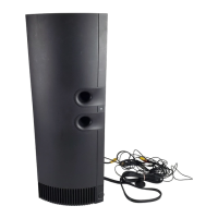
Physical
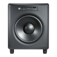
Finish: Dark graphite
Handles: Two, fl ush mounted on sides
Low Frequency Vent:
Bottom ported linear dynamics aperture
Baffl e Construction: Injection-molded structural ABS
Enclosure Construction: 25 mm (1 in) MDF; 50 mm (2”) MDF woofer baffl e
Net Weight:
29.5 kg (66 lbs)
Dimensions (WxHxD):
406 mm x 502 mm x 489 mm
(16” x 19.75” x 19.25”)
Notes:
All measurements unless otherwise stated made anechoically in a 4p environment at 2 meters, referenced to 1 meter by inverse
ce measurement microphone position is located perpendicular to the centerline of the low frequency transducer.
Acoustic loading provided by
the listening room increases maximum SPL capability and low frequency bass extension as
compared to stated anechoic values.
on measurements performed with the input voltage necessary to produce the stated A- weighted SPL at the stated
measurement distance. Distortion fi gures refer to the maximum distortion measured in any 1/10th octave wide band in the stated
lly engages in research related to performance improvements. New materials, pro duction methods, and design
refi nements are introduced into existing products without notice as a routine expression of that philosophy. For this reason, any
current JBL product may differ in some respect from its published description, but will always equal or exceed the original design
specifi cation unless otherwise stated.