Do you have a question about the JBL SUB125a and is the answer not in the manual?
Connect Left, Center, and Right speakers to these terminals.
High-level inputs for receivers without 'pre-amp out' or 'subwoofer out'.
Left and right inputs for receivers with line-level 'pre-amp out'.
Sets amplifier mode for auto turn-on/off.
Knob that controls the subwoofer's volume level.
Red and Green LEDs indicate subwoofer status.
Master power switch to disconnect the amplifier.
Details on fuse type and AC power cord connection.
Basic operational tests for line and speaker level inputs.
Testing with a sweep generator for cabinet noises.
Testing driver DC resistance and noise.
Troubleshooting steps for no sound from speakers.
Troubleshooting system shutoff at increased volumes.
Troubleshooting steps for low bass output.
Troubleshooting no sound from surround speakers.
| Frequency Response | 35Hz – 120Hz |
|---|---|
| Amplifier Power | 125W |
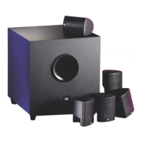
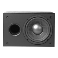
| Type | Active Subwoofer |
| Power Output | 125W |
| Driver Size | 12-inch |
| Input Connections | RCA, Speaker Level |
| Enclosure Type | Bass Reflex |
| Inputs | Line-level, Speaker-level |