· 4 · · 5 ·
MANUAL OF INSTRUCTIONS
ENG
PRODUCT DESCRIPTION
Tool kit designed to replace correctly and quickly self-adjusting clutches (SAC).
It allows tension of the diaphragm spring while installing and removing self-adjusting clutches.
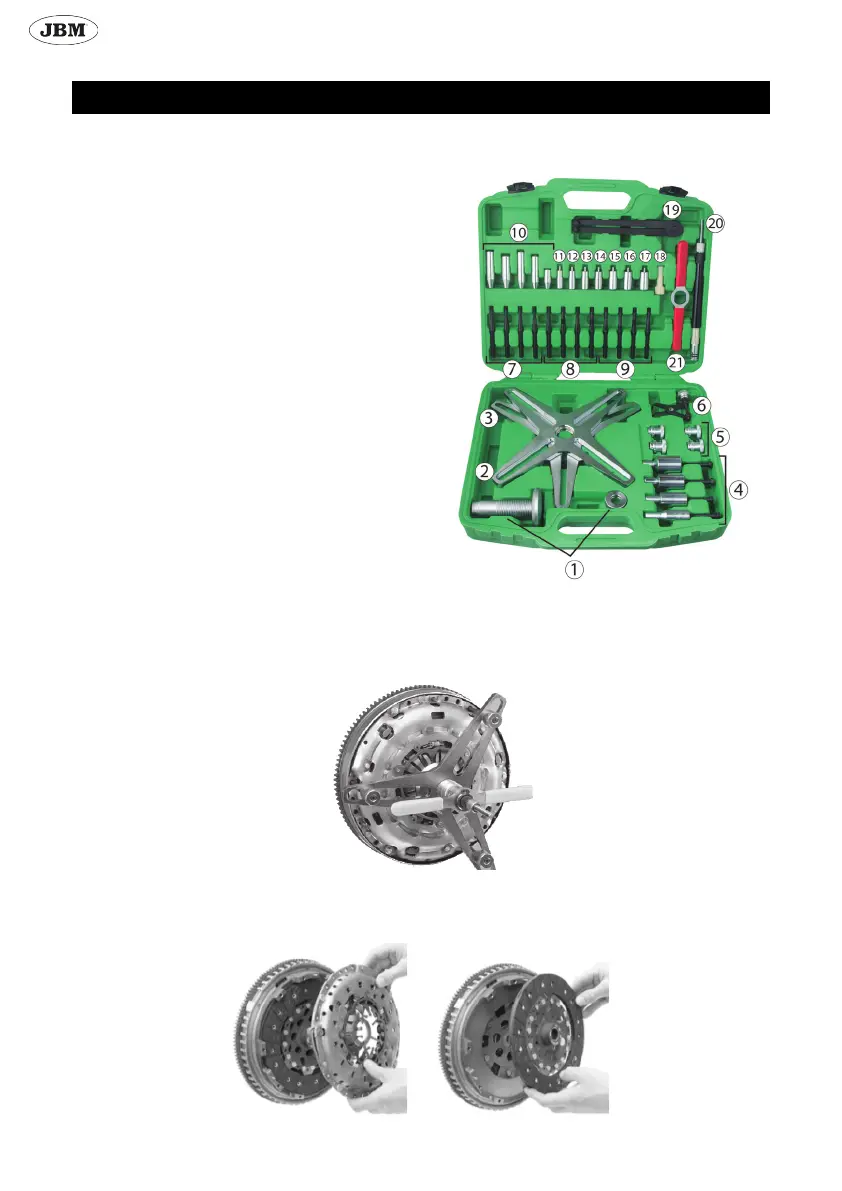
CONTENTS LIST
1. Pressure bolt
2. Alignment plate with 4 hole pitch
3. Alignment plate with 3 hole pitch
4. Centering tool: 15/23, 15/26, 15/28, 15/34
5. Special nuts
6. Clutch reset tool
7. M6 stud
8. M7 stud
9. M8 stud
19. Adjustable face spanner
21. Handle
Centering tool:
10. Centering cones
11. Ø 12mm centering pin
12. Ø 14mm centering pin
13. Ø 15mm centering pin
14. Ø 16mm centering pin
15. Ø 17mm centering pin
16. Ø 18mm centering pin
17. Ø 19mm centering pin
18. Expandable cone
20. Clutch centering tool
REMOVAL
- Remove fastening screws from the clutch pressure plate (if it has 6 screws remove 3, if it has 8 screws remove 4).
- Take 3 or 4 studs, depending on how many screw you removed, and screw the suitable studs where the screws where.
- Choose the suitable alignment plate, with 3 or 4 holes, depending on how many screws did you removed. Screw in the alignment
plate the pressure bolt.
- Insert the alignment plate into the studs.
- Screw in special nuts to keep alignment plate well xed.
- Turn the handle clockwise direction until the diaphragm spring is completely under pressure.
- Unscrew the screws that are still in the clutch pressure plate.
- Turn the handle anti-clockwise and remove the alignment plate, studs and centering tool.
- Remove clutch pressure plate and clutch disc.