About the Product
Operator Station
18 9821/9100-5 18
Operator Station
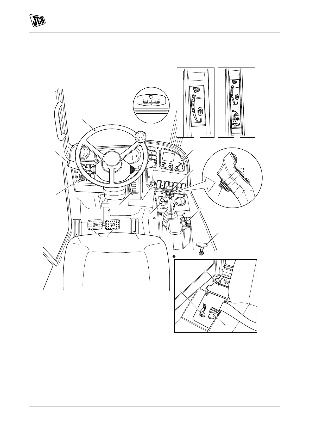
Component Locations
Figure 12.
A Steering wheel Refer to: Operation > Drive
Controls > Steering Wheel (Page 62).
B Transmission lever and gear selection
C Steer mode selector Refer to: Operation > Drive
Controls > Steer Mode Control (Page 67).
D Steering column adjustment Refer to:
Operation > Drive Controls > Steering Column
(Page 62).
E Starter switch Refer to: About the Product
> Interior Switches > Ignition Switch
(Page 25).
F HVAC (Heating Ventilation Air Conditioning)
controls Refer to: Operation > Heating,
Ventilating and Air-Conditioning (HVAC)
(Page 116).
G Service brake pedal Refer to: Operation > Drive
Controls > Service Brake Pedal (Page 64).
H Accelerator pedal Refer to: Operation > Drive
Controls > Accelerator Pedal (Page 62).