06 - Body and Framework
03 - Chassis
36 - Upper Crossmember
06 - 9 9813/8950-2 06 - 9
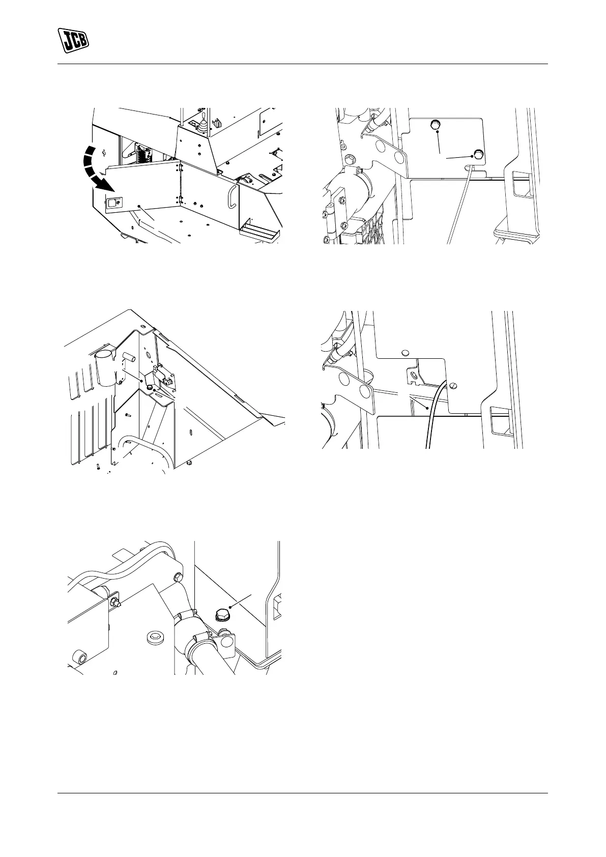
Figure 17.
A Side access panel
4. Remove the top bolts 1 from the engine
compartment cover.
Figure 18.
B Bolts 1
5. Remove the bolts 2 from the upper
crossmember.
Figure 19.
C Bolts 2
6. Remove the bolts 3 from the reverse alarm cover.
Figure 20.
D Bolts 3
7. Disconnect the reverse alarm electrical
connector.
Figure 21.
E Electrical connector
8. Support the upper crossmember with suitable
lifting equipment.
9. Remove the upper crossmember from the
machine.