About the Product
Operator Station
17 9821/6200-7 17
Operator Station
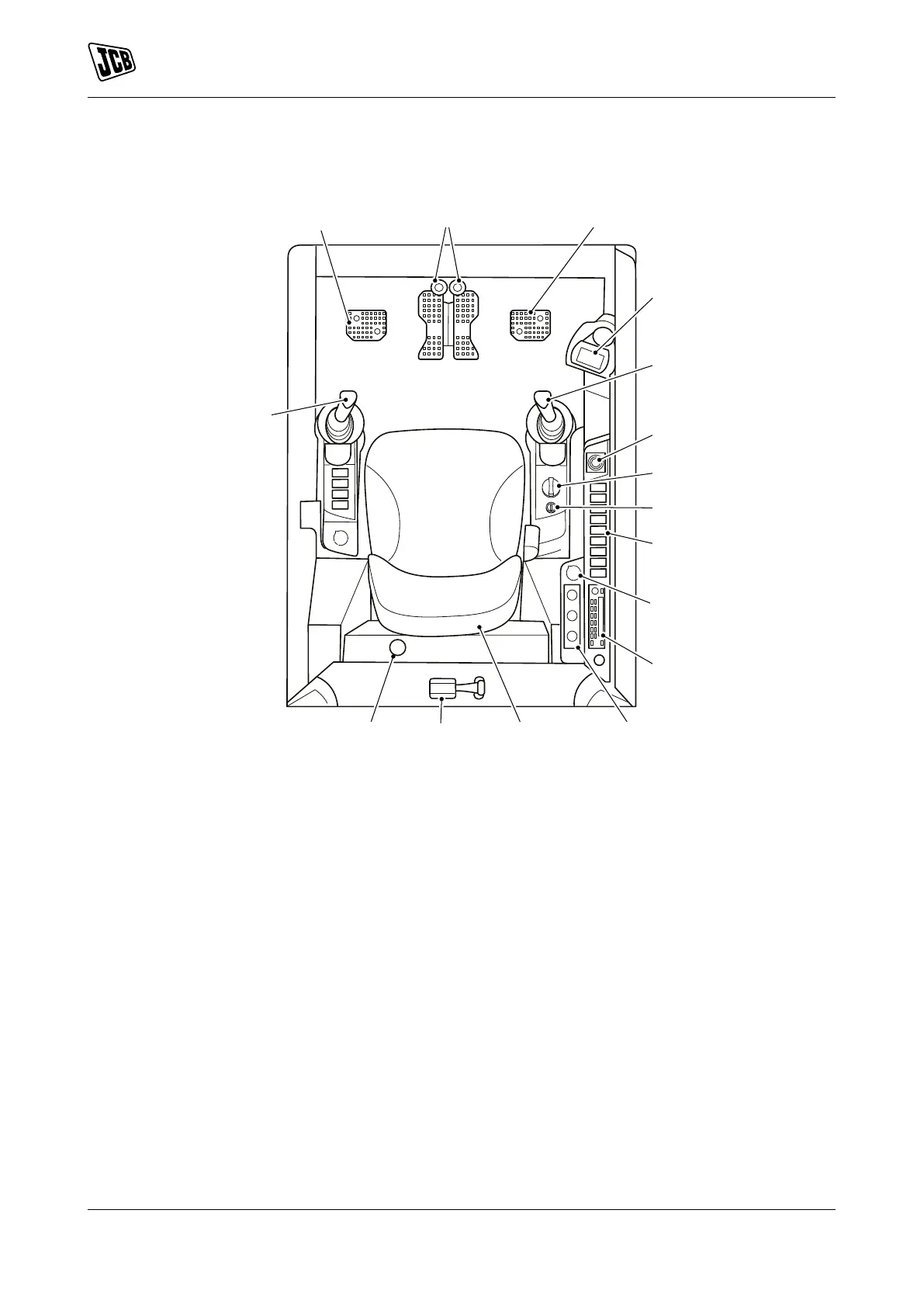
Component Locations
Figure 11.
A Track controls Refer to: Track Controls
(Page 59).
B Swing control pedal Refer to: Excavator End
Controls (Page 73).
C Instrument panel Refer to: Instruments
(Page 60).
D Excavator controls Refer to: Excavator End
Controls (Page 73).
E Dozer blade control lever Refer to: Dozer Blade
Controls (Page 76).
F Two-speed tracking switch Refer to: Track
Controls (Page 59).
G Hand throttle control Refer to: Hand Throttle
Control (Page 59).
H Ignition key switch Refer to: Ignition Switch
(Page 18).
J Switch console Refer to: Console Switches
(Page 20).
K Auxiliary power socket Refer to: Power Sockets
(Page 89).
L Entertainment system M HVAC (Heating Ventilation Air Conditioning)
controls Refer to: Heating, Ventilating and Air-
Conditioning (HVAC) (Page 87).
N Operator seat Refer to: Operator Seat
(Page 41).
P Glass hammer Refer to: Emergency Exit
(Page 31).
Q Fire extinguisher (option)Refer to: Fire
Extinguisher (Page 90).
R TAB (Triple Articulated Boom) pedalRefer to:
Excavator End Controls (Page 73).