G2
A. ADJUSTING THE CUTTING
ANGLE (See E&F)
Turn the base plate bevel lock (6)
in counter-clockwise direction to
loosen the angle scale. Tilt the
base plate away from the machine
until the required cutting angle is
adjusted on the bevel scale (4).
Tighten the bevel lock button(6) by
turning it in clockwise direction.
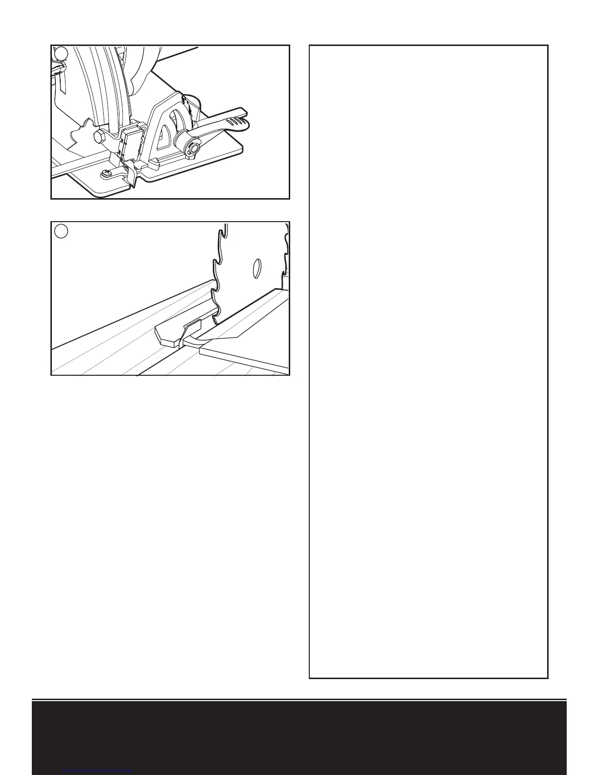
B. CUTTING GUIDE (See G1, G2)
The sight line (G2) fixed in front of
the base plate is used as cutting
guide. Always guide it along the
cutting mark made on the workpiece
for accurate cutting.
The cutting mark 0° indicates the
position of the saw blade for right-
angled cuts.
NOTE:
It is best to perform a
practice cut prior to starting work.
8. PARALLEL GUIDE
ADJUSTMENT
Used for making cuts parallel to
a work piece edge at a chosen
distance. Slide the parallel guide
arm through both fixtures to achieve
the required cutting distance and
tighten screw to lock into position
(See H2). It can be used from both
sides of the base plate (15). There is
a cutting guide notch on the front of
the base plate (15) for using with a
parallel guide (10). For straight cuts,
use the 0° guide mark to align with
G1