6 - 2
Throttle Motor and Throttle Link
Replacement (continued)
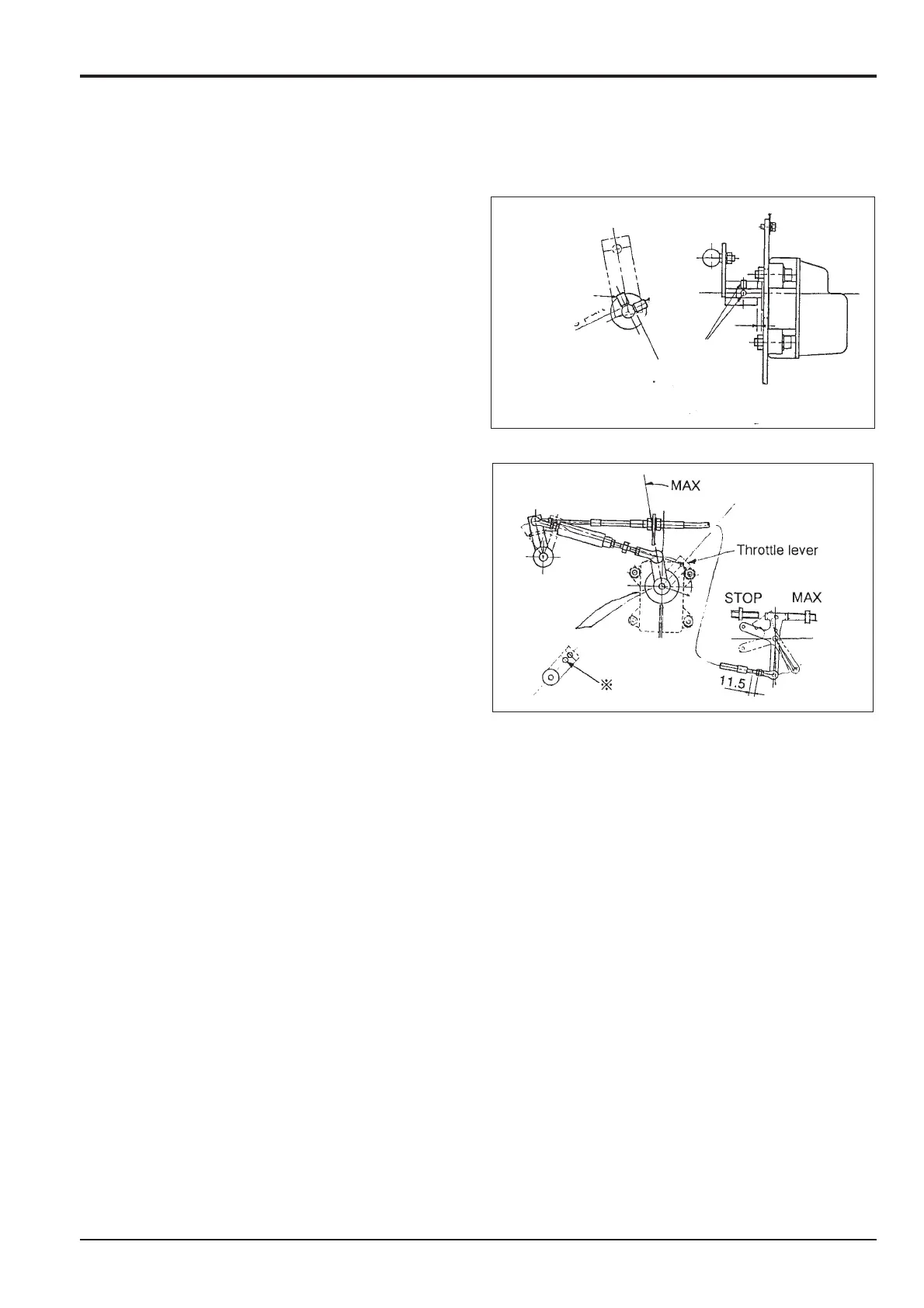
7 Installation of the throttle link lever
a Install the lever on the new throttle motor without
forcing it.
b Coat the screws D with loctite before fastening.
8 Installation of the throttle link
a After installation of the throttle motor, install the
throttle links to the throttle lever and the control link.
9 Adjustment of Throttle Link
a Switch it to redundancy.
b Adjust the link of the engine side of the governor so
that it hits the stopper bolt on the Max side of the
throttle UP switch.
c After checking that it does hit the screw, rotate the
spring chamber out 3 Complete rotations (counter
clockwise) from that position.
d Adjust the length of the link so that the stroke of the
spring chamber is 1.5-5mm.
10 Confirmation of Throttle Motor Operations
a Confirm that the 'electric system abnormality' is not
displayed in the monitor when the key switch is ON.
b With the throttle volume at engine MAX position,
confirm that the spring chamber contracts, after the
link of the engine side governor hits the stop.
c At the STOP side, with the throttle volume knob at
the engine MIN position, confirm that the spring
chamber contracts after the key switch is OFF.
Note: Perform the automatic adjustment after confirmation
of the above adjustment.
Section C Electrics
9803/6410
Section C
6 - 2
Issue 1
Throttle Motor
D
D
D