10 - 2
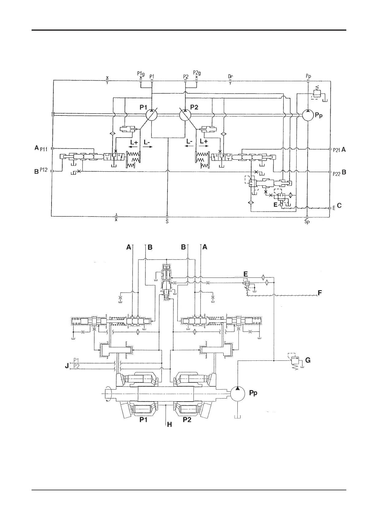
Pump Hydraulic Circuit Diagram
Pump Configuration
Section E Hydraulics
9803/6410
Section E
10 - 2
Issue 1
Hydraulic Pump/Regulator
JS00040
JS00050
Key
A Negative control signal
B Maximum flow signal
C Mode change - electrical signal
E Solenoid proportional pressure control (SPPC) valve
F Total horsepower control electrical signal
G Pilot pressure relief valve
H Pump input
J Pump outputs
L Swash plate angle
P1 Front pump
P2 Rear pump
Pp Pilot pump