Assembly (cont’d)
When Assembling (cont’d)
8 Tighten the plug and bolts to the torques indicated
below:
Adjustments
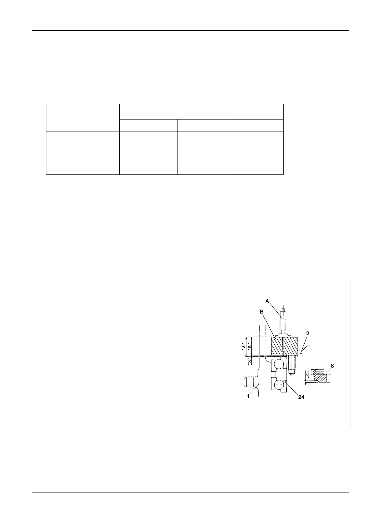
Determining the Thickness of Distance Piece 12
This procedure must be carried out if any of the following
components have been renewed: hub 1, spindle 2, ring gear
4, coupling gear 8, pin 17, bearings 24 or parallel pins 27.
1 Install the distance piece clearance gauge B (see
Service Tools, Section 1) in spindle 2 in place of
distance piece 12.
2 Lightly tighten three evenly spaced bolts 35.
3 Measure dimension ‘A’ with depth micrometer as
shown.
4 Measure dimension ‘C’ of the assembled coupling gear
8.
5 Clearance X = A - B, where ‘B’ is the dimension of
gauge B.
Calculate the optimum thickness ‘T’ of distance piece
12 as follows:
T = C + X ± 0.1 mm
10 - 8
Section F Transmission
9803/6410
Section F
10 - 8
Issue 1
Reduction Gear - JS160
JS00660
Torques
Part
Nm lbf ft kgf m
Plug 30 59 ± 20 43.4 ± 14.5 6 ± 2
Bolt 32 102 ± 15.7 75.2 ± 11.6 10.4 ± 1.6
Bolt 35 348 ± 54 257 ± 40 35 ± 5.5