14 - 1
Dismantling
Refer to the drawing on the previous pages of the pump and
associated components.
Before attempting to dismantle the hydraulic pump, drain all
oil, blank all inlet and outlet ports and wash the outer
surfaces with a suitable solvent to remove all dirt and dust.
Dry using compressed air.
Make different alignment marks across each sub-assembly
joint face as an aid to assembly.
The rotary groups, servo pump, relief valve and proportional
pressure reduction valve must be replaced as entire
assemblies.
1. Remove the drain port plugs and drain the oil from both
the front and rear pump.
2. Remove the hexagonal socket head bolts (412, 413) and
remove the regulator (refer to the regulator maintenance
section for the disassembly procedures).
3. Loosen the hexagonal socket head bolt (401) which
connects the swash plate support (251), pump casing
(217) and valve block (312). If the gear pump etc. are
attached to the back of the pump, remove them first.
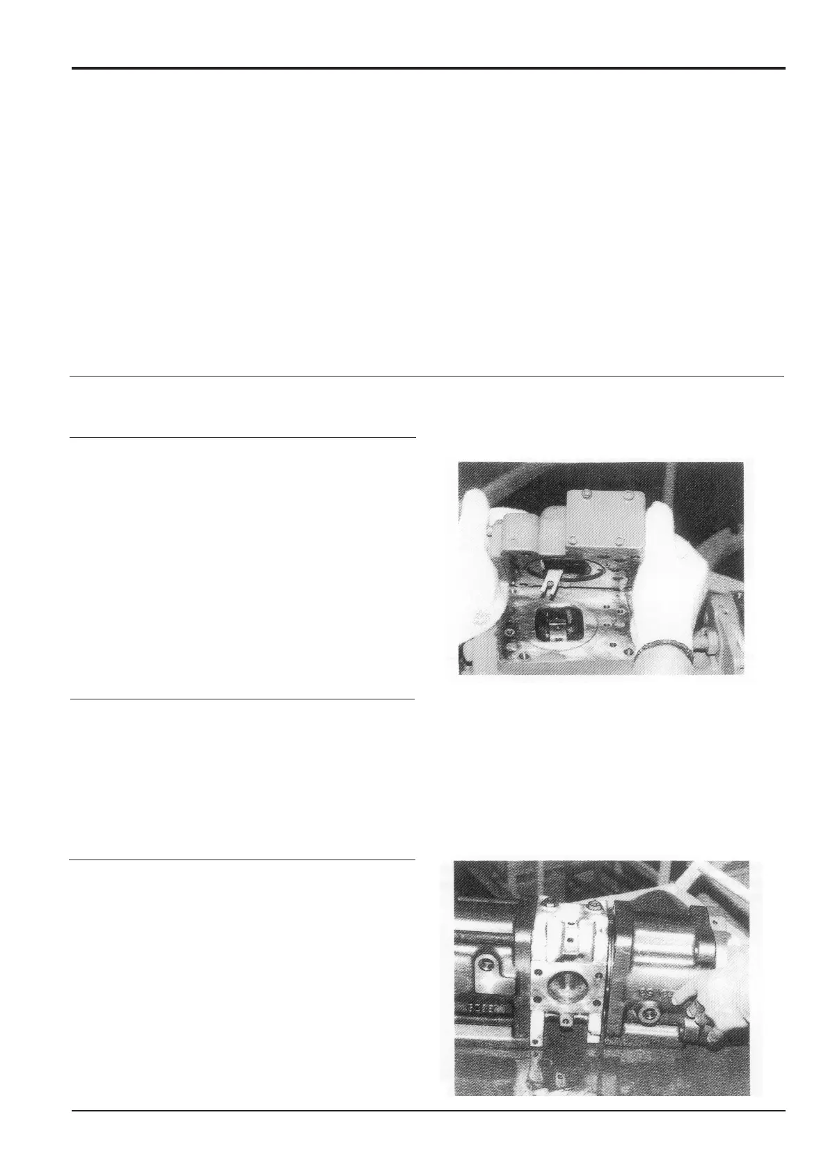
4. Place the pump so that the regulator installation side is
down and place level on the work bench. Separate the
pump casing (271) and valve block (312).
Section E
Hydraulics
9803/6400
Section E
14 - 1
Issue 1
Hydraulic Pump JS200, JS240
Adjusting screws should only be moved when absolutely
necessary. Moving the adjusting screws will alter the power
output settings. If the adjusting screws must be moved,
measure and record the dimensions and positions.
The pump contains two rotary groups and control systems;
the No.1 (subsidiary) pump and the No.2 (drive) pump. Take
care not to confuse parts between the two.
During disassembly, record the number and dimensions of
shims. Take care to reassemble in the same manner.