23 - 1
Regulator Disassembly
Refer to the sectional drawings at the beginning of this
section.
Before dismantling, blank all inlet and outlet ports and wash
the outer surfaces with a suitable solvent to remove all dirt
and dust. Dry using compressed air.
Adjusting screws should only be moved when absolutely
necessary. Moving the adjusting screw will alter the power
output settings. If the adjusting screws must be moved,
measure and record the dimensions and positions.
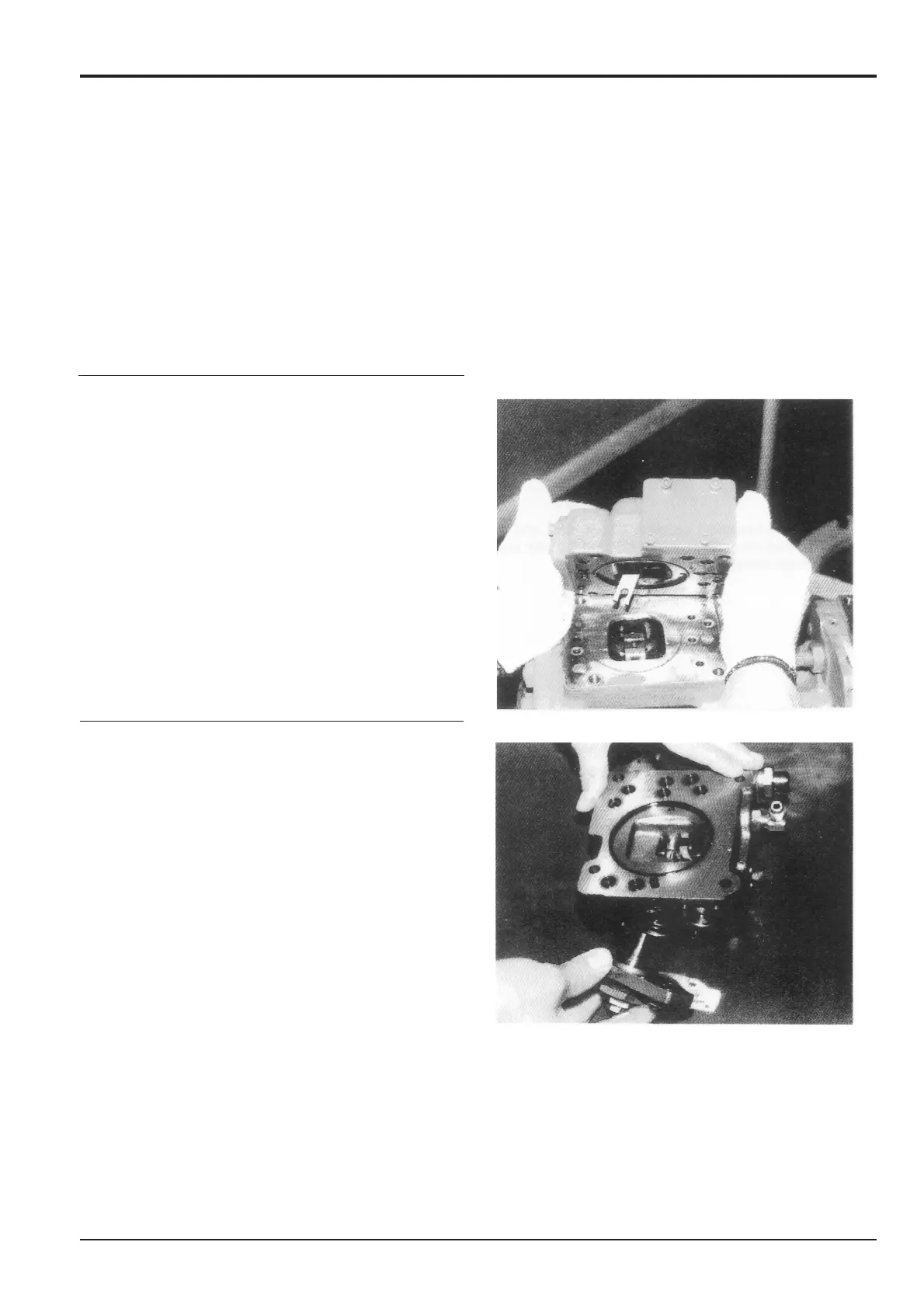
1. Remove the hexagonal socket head bolts (412, 413) and
remove the pump main body from the regulator.
2. Remove the hexagonal socket head bolt (438) and
remove the cover (C) (629).
Note: Adjusting screws (C), (CI) (628, 925), adjusting ring (C)
(672), lock nut (630), hexagonal nut (801), adjusting screw
(921) is assembled on the cover (C). Do not loosen these
nuts and screws, for the adjusted pressure and flow rate
setting will be changed.
Section E
Hydraulics
9803/6400
Section E
23 - 1
Issue 1
Regulator JS200. JS240