23 - 5
Regulator Assembly
Clean each part in a suitable solvent and dry using
compressed air.
Inspect all parts and replace as required.
Care must be taken not to let dust or dirt adhere to parts after
cleaning and that parts do not become dented, scratched or
damaged.
Fit new 'O' rings, plugs, packing and oil seals, and apply
clean hydraulic fluid to all sliding parts before installation.
1. Assemble the compensatory rod (623) into the
compensatory hole of the casing (601).
2. Insert the pin which is press-fitted into the lever (1) (612)
into the compensatory rod groove and assemble the pin
which is press-fitted into the casing to the lever (1).
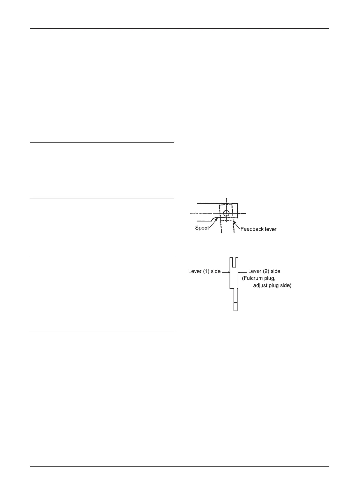
3. Assemble the spool (652) and sleeve (651) into the
spool hole of the casing.
Note: (1) Confirm that the spool and sleeve slide smoothly
inside the casing. (2) Be careful of the spool direction.
4. Assemble the feedback lever (611) and insert the pin
(874), aligning with the feedback pin hole.
Note: (1) To facilitate work, insert the pin a little into the
feedback lever beforehand. (2) Be careful not to mistake the
direction of the feedback lever.
5. Assemble the pilot piston (643) to the casing hole for
flow rate control.
Note: (1) Confirm that the pilot piston slides smoothly.
All tapped holes and gasket faces should be thoroughly
degreased by washing as liquid packing and adhesive is
used on all gasket surfaces and threads.
Apply adhesive to the final few threads of a bolt or screw. Do
not apply excessive amounts of adhesive. Wipe off any
surplus liquid packing.
Ensure that the pump controllers are fitted to the positions
from which they were removed.
Section E
Hydraulics
9803/6400
Section E
23 - 5
Issue 2*
Regulator JS200. JS240
*