3 - 7
Section F
Transmission
9803/6400
Section F
3 - 7
Issue 1
Motor/Gearbox
Operation (continued)
Relief Valve (continued)
The relief valve works in the following two stages.
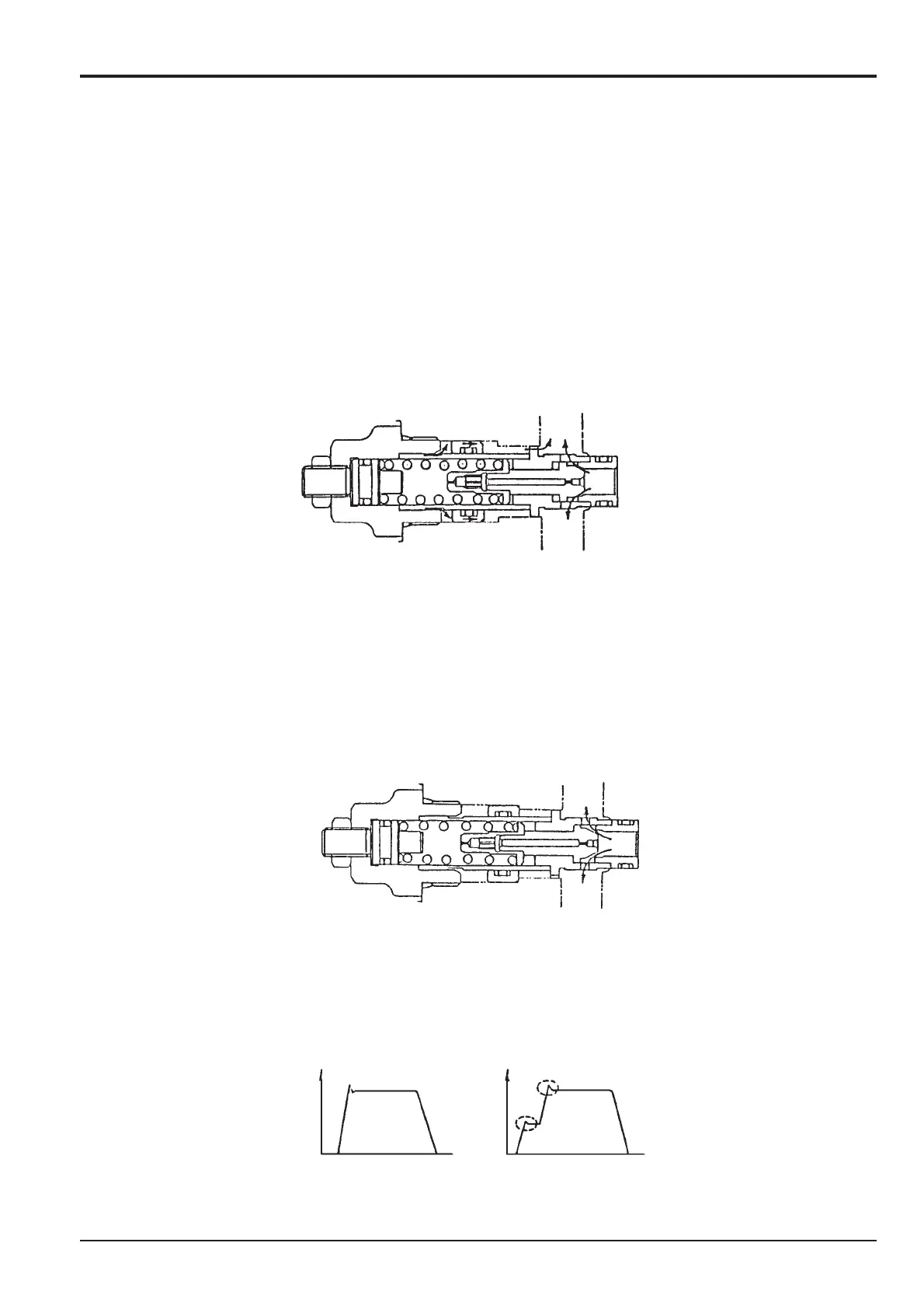
First Stage: Refer to Fig. 6-1
When the relief valve starts operating, the shockless piston moves to keep the spring cavity at low pressure. The
pressure receiving area of the poppet equals the area of the poppet seat (S1) and so it is considerably larger than the
pressure receiving area (S1-S2) when the relief is normally set. Since the relief operating pressure in this state is low, it is kept
at low pressure (about on third of the normally set pressure). The low pressure holding time depends on the poppet orifice
diameter, the shockless piston pressure receiving area and the piston stroke.
Fig. 6-1 First Stage of Relief Valve Working
Second Stage: Refer to Fig. 6-2
When the movement of the shockless piston is completed, the pressure in the spring cavity of the relief valve increases to
make the pressures on both sides of the poppet equal. Accordingly, the relief valve works at the normal set pressure.
Fig. 6-2 Second Stage of Relief Valve Working
Below is a comparison of the normal type and shockless type.