About the Product
Operator Station
15 9831/1450-1 15
Operator Station
Component Locations
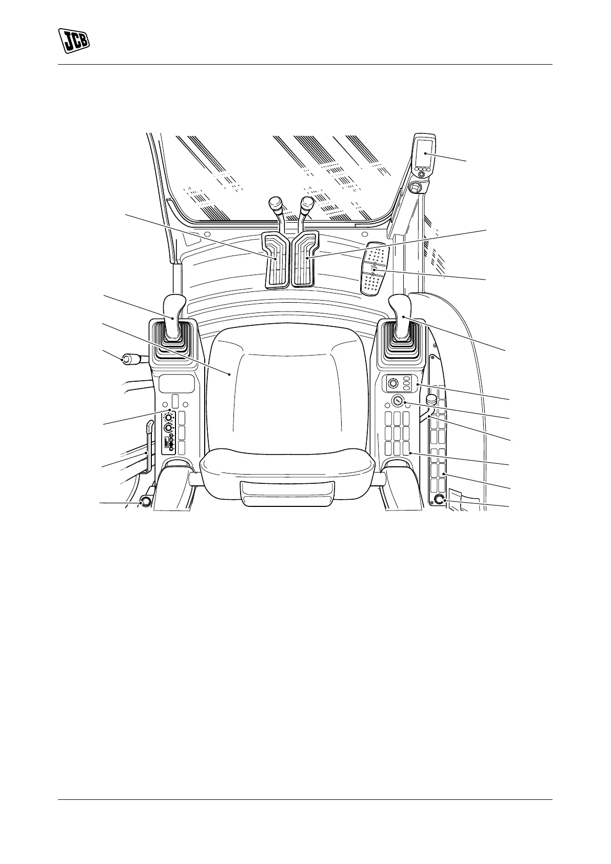
Figure 11.
A Left hand track control, Refer to:
Operation > Drive Controls > Track
Controls (Page 58).
B DECU (Display Electronic Control Unit),
Refer to: Operation > Instruments >
Instrument Panel (Page 62).
C Right hand track control, Refer to:
Operation > Drive Controls > Track
Controls (Page 58).
D Optional circuit pedal, Refer to: Operation
> Operating Levers/Pedals > Auxiliary
Circuit Controls (Page 85).
E Right joystick, Refer to: Operation >
Operating Levers/Pedals > Excavator
Arm Controls (Page 80).
F Machine power band controller, Refer
to: Operation > Instruments > General
(Page 61).
G Ignition switch, Refer to: About the
Product > Interior Switches > Ignition
Switch (Page 19).
H Dozer lever,
J Right switch console, Refer to: About
the Product > Console Switches
(Page 17).
K 12V auxiliary power socket, Refer to:
Operation > Power Sockets > Auxiliary
Power Socket (Page 107).
L Door lever, Refer to: Operation > Doors >
Operator Door (Page 31).
M Left switch console, Refer to: About
the Product > Console Switches
(Page 17).
N Controls isolation lever,Refer to:
Operation > Safety Equipment > Control
Lock (Page 56).
P Seat, Refer to: Operation > Operator
Seat (Page 40).