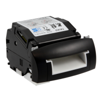
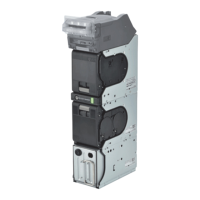
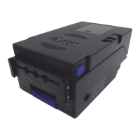
DBV
TM
200: Auto-Calibration
1. Power Off
2. Set DIP Switch DS2: 4,5, and 6 “On.”
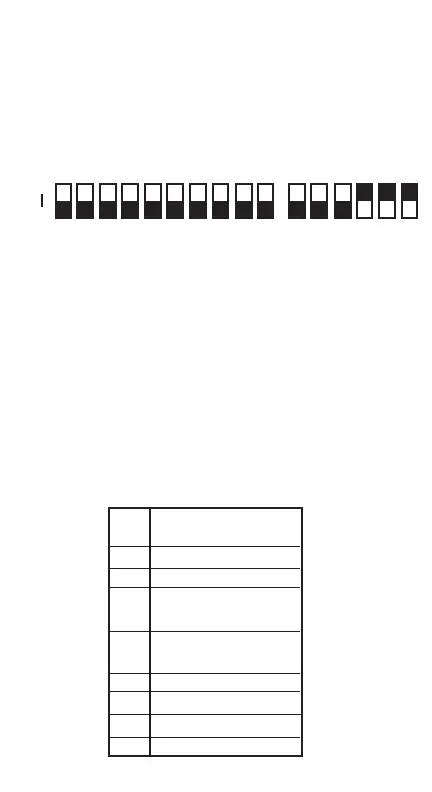
DS1 DS2
On
Off
12345678910 123456
Denomination/Interface use Diagnostic Use
3. Power-on Unit (plug in the 6-pin connector)
4. Head motor will cycle and stop - Ready to Calibrate
5. Insert the DBV-200 calibration paper, black side first (Part No.
057619).
After inserting the calibration paper, the unit will carry the paper for-
ward/reverse several times. When the process is complete, the unit will
return the paper.
Look at the indicator for proper signals: 14-pin Test LED, or the bezel
light, if used. Fast Blinks indicate acceptable calibration, and Blinks from
1-11 at intervals of 1/2 second indicate an error as described below.
# of
Blinks
Error Found
During Calibration
1 Entrance Level Error
3 Entrance Sensor Error
5 Gain Error
White Level Adjustments
6 Digital/Analog Error
White Level Adjustments
7 Barcode Sensor Error
9 Magnetic Setting Error
10 Write-in Error
11 Black Level Error