Do you have a question about the JCM ivizion ld and is the answer not in the manual?
Introduces the different specifications of iVIZION units.
Details the model number specifications for iVIZION units.
Lists and defines the product type number specifications.
Details the software specifications for iVIZION units.
Presents safety symbols, user cautions, and installation cautions.
Details methods for mounting, dismounting, and transporting the unit.
Precautions for foreign objects and conditions of unacceptable banknotes.
Describes the recommended preventive maintenance procedures for the unit.
Guidelines for handling reference paper used in calibration.
Highlights the main features of the iVIZION Series Banknote Acceptor.
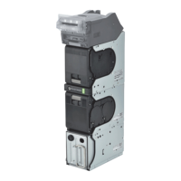
Identifies the names and locations of iVIZION components.
Lists the technical specifications for SS/SH models.
Details environmental, electrical, structural, and RFID specs for SS/SH.
Lists the technical specifications for the iVIZION LD model.
Details electrical and structural specs for the iVIZION LD model.
Covers outside and installation/maintenance dimensions for SS models.
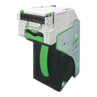
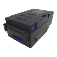
Illustrates the outside dimensions of the iVIZION LD unit.
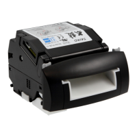
Illustrates the outside dimensions of the iVIZION SH unit.
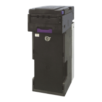
Illustrates dimensions for standard, large, and HC cash boxes.
Step-by-step guide for installing the iVIZION unit.
Details how to install, use, and unlock security locks on the cash box.
Explains the settings for denomination inhibit and software DIP switches.
Describes the meaning of different LED status and error indications.
Lists pin assignments for various connectors (USB, Photo-Coupler, etc.).
Covers retrieving banknotes, clearing jams, and cleaning procedures.
Specific installation steps for the iVIZION LD version unit.
Identifies the locations of various sensors within the unit.
Shows schematic diagrams for USB, Photo-Coupler, RS232C, ccTalk, TTL, LED.
Depicts initialization and validation flow processes for iVIZION units.
Lists the necessary tools for disassembly and reassembly.
Steps to remove the timing belt from the pusher unit.
Instructions for removing stacker guides and frame outer parts.
Instructions for removing the pusher mechanism and guide.
Steps to remove the transport unit's bottom and side covers.
Instructions for removing sensor boards, RFID module, and CPU boards.
Steps for removing USB, Power, Interface FPC cables and harnesses.
Instructions for removing the timing belt from the motor unit.
Steps to remove stacker/transport motors and sensor assemblies.
Instructions for removing the validation sensor board assembly.
Instructions for removing CIS, Transmissive Light, and Upper UV sensors.
Steps to remove CIS, CIS FPC, Lower UV Sensor, and Lower UV FFC.
Instructions for removing the timing belt from the validation unit.
Notes and warnings to follow during the reassembly process.
Lists tools and equipment needed for installation and downloading.
Details the procedure for installing the JCM Tool Suite Standard Edition.
Steps to install the necessary iVIZION USB drivers.
Explains the Normal and Test modes of the JCM Tool Suite.
Outlines procedures for downloading software, including upgrades.
Instructions for performing unit sensor calibration and serial number writing.
Explains methods for performing performance tests using PC or DIP switches.
Steps to set ICB enable/disable, machine number, and inhibit functions.
Instructions for testing the DIP switch functions.
Information on using utility tools for CIS image views and ICB functions.
Shows exploded view and parts list for the entire iVIZION unit.
Exploded views and parts lists for Validation Units 1, 2, and 3.
Exploded views and parts lists for Transport Units 1 through 6.
Exploded view and parts list for the SS version frame unit.
Exploded views and parts lists for Cash Box Units 1, 2, and 3.
Exploded view and parts list for the iVIZION LD frame.
Exploded view and parts list for the iVIZION HC frame.
Exploded views and parts lists for HC Box Assembly and Unit.
Exploded view and parts list for the HC Upper Part.
Exploded view and parts list for the HC Receive Plate Assembly.
Exploded view and parts list for the HC Receive Spring Base Assembly.
Exploded view and parts list for the HC Front Plate Assembly.
Exploded view and parts list for the HC Pusher Unit.
Exploded views and parts lists for HC Pusher Assemblies 1 and 2.
Exploded views of optional bezels, harnesses, wave rubber, and sorting pusher units.
Introduces troubleshooting and explains fault diagnosis methods.
Details LED error codes, indications, and their causes/solutions.
Lists LED jam flash code causes and solutions.
Lists LED reject error flash code causes and solutions.
Lists barcode coupon and calibration error code causes and solutions.
| Brand | JCM |
|---|---|
| Model | ivizion ld |
| Category | Banknote Counter |
| Language | English |