CONFIDENTIAL PROPERTY OF JCM GLOBAL DRAFT 5 © 2010, Japan CashMachine Co, Limited
5
iVIZION™ Series Next-Generation Banknote Acceptor Integration Guide
Cable Interconnection
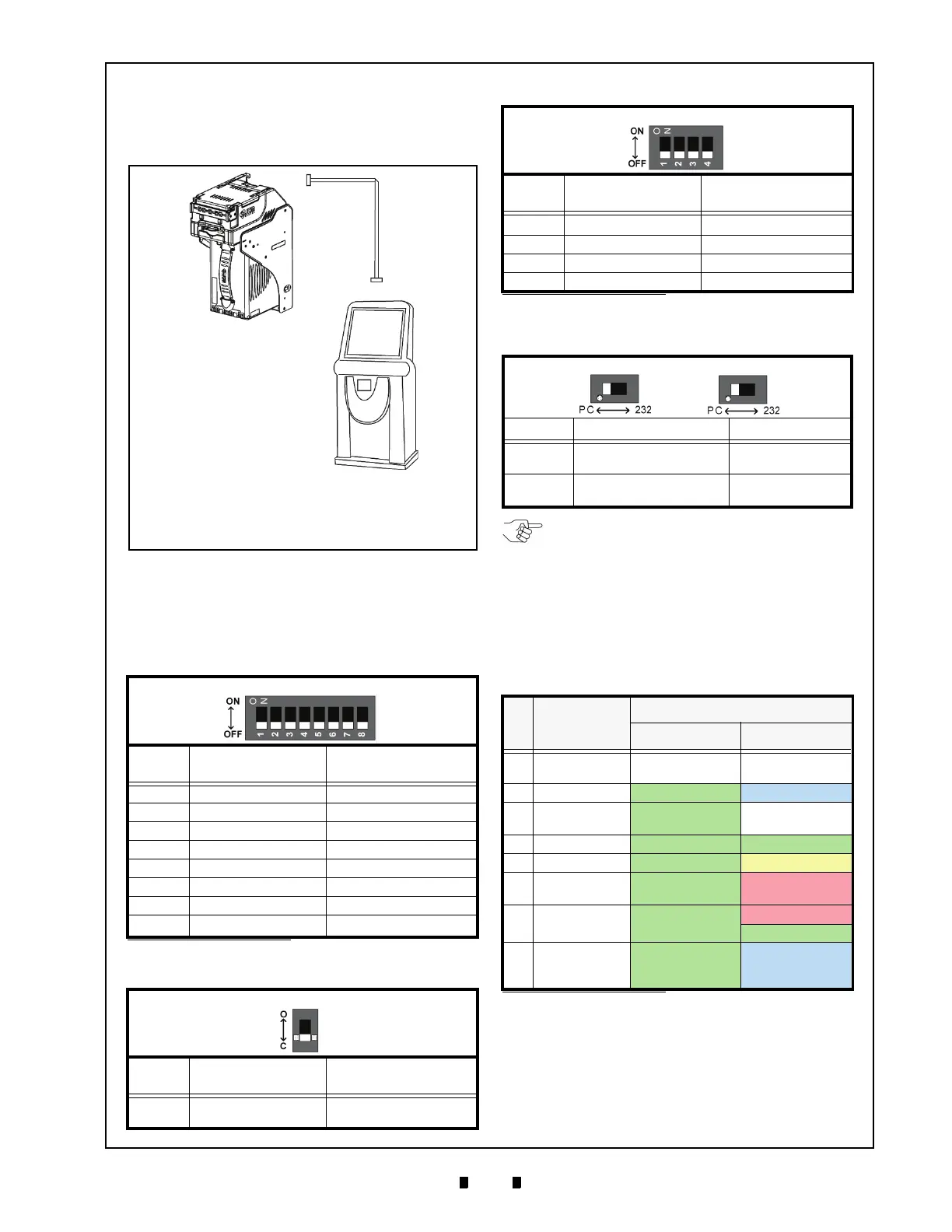
Figure 6 illustrates the Cable Harness interconnect-
ion requirements between the iVIZION™ and a
Host Machine.
DIP Switch Configurations
This portion provides the denomination DIP Switch
Block Settings for the iVIZION™ Unit.
P
RIMARY
LED I
NDICATIONS
The iVIZION™ Unit pair of Color LED indications
appear when various operating and error conditions
occur.
Table 5 Denomination INHIBIT DIP Switch Settings
Validation CPU Board SW1
Switch
No.
Switch ON Switch OFF
1 VEND 1 INHIBIT VEND 1 ACCEPT
2 VEND 2 INHIBIT VEND 2 ACCEPT
3 VEND 3 INHIBIT VEND 3 ACCEPT
4 VEND 4 INHIBIT VEND 4 ACCEPT
5 VEND 5 INHIBIT VEND 5 ACCEPT
6 VEND 6 INHIBIT VEND 6 ACCEPT
7 VEND 7 INHIBIT VEND 7 ACCEPT
8
N/A
*
*. Not Applicable (N/A). Never Switched to ON.
OFF (Fixed)
Table 6 JCM Private Line DIP Switch Setting
Validation CPU Board JP1
Switch
No.
Non-Marked (
O) Marked (C)
1
RS-485 Terminating
Resistance Open
RS-485 Terminating
Resistance Closed
a
b
c
d
a) iVIZION™ Unit
b) Interface Connector (iVIZION™)
c) Harness
d) Host Machine (Game Machine, Jute Box, Kiosk,
etc.)
Figure 6 Cable Interconnection
Table 7 Software DIP Switch Settings
Control CPU Board SW1
Switch
No.
Swit
ch ON Switch OFF
1
N/A
*
*. Not Applicable (N/A). Never Switched to ON.
OFF (Fixed)
2 N/A* OFF (Fixed)
3 N/A* OFF (Fixed)
4 N/A* OFF (Fixed)
Table 8 Serial Communications DIP Switch
Settings
Control CPU Board JP2 & JP3
Switch No. Marked Non-Marked
JP2
Photo-Coupler
Isolation (Standard)
RS232
JP3
Photo-Coupler
Isolation (S
tandard)
RS232
Table 9 LED Error Pattern Indications
No. Condition
LED Indications
Power LED
*
*. The Power LED lights when Power is supplied to the Unit.
Status LED
1 OFF
Extinguished
(OUT)
Extinguish
ed
(OUT)
2
Initializing Green Lit Blue Flashes
3
Stand-by Green Lit
Extinguished
(OUT)
4
Reject Green Lit Green Flashes
5
Banknote Jam Green Lit Yellow Flashes
6
Abnormal
Error
Green Lit Red Flashes
7 Downloading Green Lit
Red Lit
Green Lit
8
Performance
Test
(Stand-by)
Green Lit Blue Lit
NOTE: When changing the type of iVIZION
Serial Communications, Switches JP2 and
JP3 located on the Control CPU Board must
be set to identical switch positions.

 Loading...


