IGNITION CONTROL
TABLE OF CONTENTS
page page
GLOW PLUG
DESCRIPTION ..........................1
OPERATION ............................1
REMOVAL .............................1
INSTALLATION ..........................1
GLOW PLUG RELAY
DESCRIPTION ..........................2
OPERATION ............................2
DIAGNOSIS AND TESTING - GLOW PLUG
RELAYS ..............................2
GLOW PLUG
DESCRIPTION
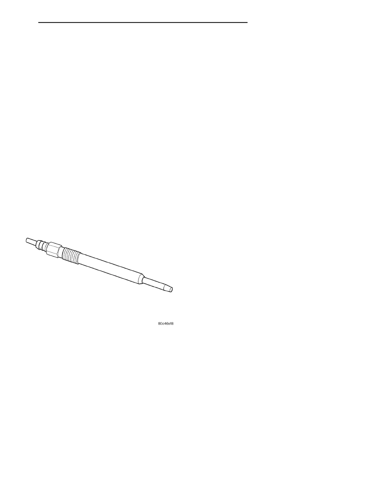
Glow plugs are used to help start a cold or cool
engine (Fig. 1). The glow plugs will heat up and glow
to heat the combustion chamber of each cylinder. An
individual glow plug is used for each cylinder. Each
glow plug is threaded into the left side of the cylinder
head below the cylinder head cover/intake manifold.
OPERATION
The glow plugs are used to preheat the combustion
chambers in order to achieve the ignition tempera-
ture required for the fuel-air mixture.
The glow plug consists of a housing with a female
thread and an interference-fit rod. The heating ele-
ment is integrated in the glow rod. It consists of a
heating winding and a control winding connected in
series.
When the glow plug system is switched “ON”, a
current of about 30 ampere flows to each glow plug.
The heating winding heats the glow plug. The control
winding increases its resistance as the temperature
rises and limits the current to approximately 15-25
ampere. The glow plug is protected this way from
overloads.
REMOVAL
CAUTION: Engine temperature must be at least
90°C (194°F) before removing glow plugs. If cylinder
head is already removed, warm cylinder head to
90°C (194°F) before removing glow plugs.
(1) Disconnect negative battery cable.
(2) Remove engine cover (Refer to 9 - ENGINE -
REMOVAL).
WARNING: NO SPARKS, OPEN FLAMES OR SMOK-
ING. RISK OF POISONING FROM INHALING OR
SWALLOWING FUEL. RISK OF INJURY TO SKIN
AND EYES EXPOSED TO FUEL. POUR FUELS ONLY
INTO SUITABLE AND APPROPRIATELY MARKED
CONTAINERS. WEAR PROTECTIVE CLOTHING.
NOTE: Press in on fuel line locking tab to release
fuel line. Pull back on locking tab to return to lock
position.
(3) Remove fuel return flow line to high pressure
pump.
(4) Disconnect glow plug electrical connector (Fig.
2).
WARNING: RISK OF INJURY TO SKIN AND EYES
FROM HANDLING HOT OR GLOWING OBJECTS.
WEAR PROTECTIVE GLOVES, CLOTHING AND EYE
WEAR.
(5) Remove glow plugs and clean glow plug bay
(Fig. 2).
INSTALLATION
(1) Clean glow plug bay and install glow plug.
Tighten glow plugs to 12N·m (106 lbs. in.).
(2) Connect glow plug electrical connector. (Fig. 2).
Fig. 1 GLOW PLUG
WG IGNITION CONTROL 8Ia - 1










 To Next Page