EasyManua.ls Logo

Jeep UNIVERSAL CJ-2A - Page 101

Jeep UNIVERSAL CJ-2A
281 pages
Print Icon
To Next Page IconTo Next Page
To Previous Page IconTo Previous Page
Loading...
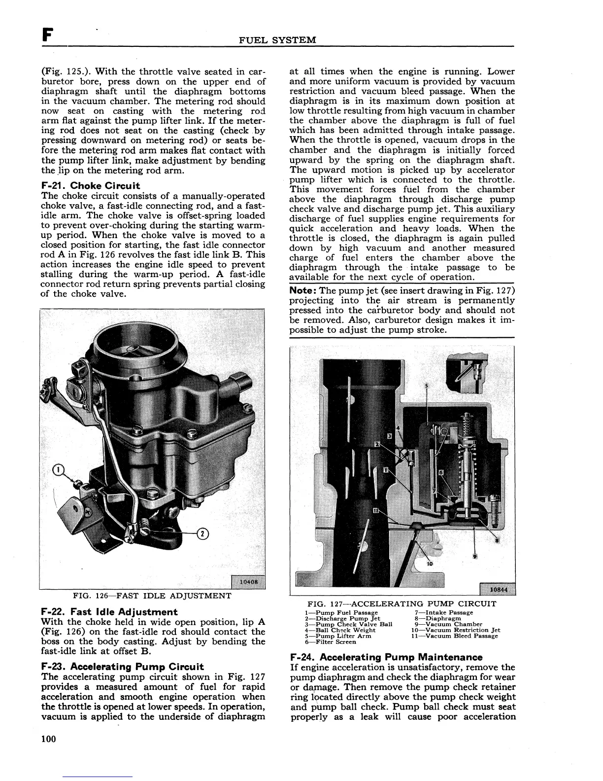
F
FUEL
SYSTEM
(Fig.
125.).
With
the
throttle
valve
seated
in
car-
buretor
bore,
press
down
on
the
upper
end
of
diaphragm
shaft
until
the
diaphragm
bottoms
in
the
vacuum
chamber.
The
metering
rod
should
now
seat
on
casting
with
the
metering
rod
arm
flat
against
the
pump
lifter
link.
If
the
meter-
ing
rod
does
not
seat
on
the
casting
(check
by
pressing
downward
on
metering
rod)
or
seats
be-
fore
the
metering
rod
arm
makes
flat
contact
with
the
pump
lifter
link,
make
adjustment
by
bending
the
.lip
on
the
metering
rod
arm.
F"
-21.
Choke
Circuit
The
choke
circuit
consists
of
a
manually-operated
choke
valve,
a fast-idle
connecting
rod,
and
a
fast-
idle
arm.
The
choke
valve
is
offset-spring
loaded
to
prevent
over-choking
during
the
starting
warm-
up
period.
When
the
choke
valve
is
moved
to
a
closed
position
for
starting,
the
fast
idle
connector
rod
A
in
Fig.
126
revolves
the
fast
idle
link
B.
This
action
increases
the
engine
idle
speed
to
prevent
stalling
during
the
warm-up
period.
A
fast-idle
connector
rod
return
spring
prevents
partial
closing
of
the
choke
valve.
FIG.
126-FAST
IDLE
ADJUSTMENT
F"-22.
Fast
Idle
Adjustment
With
the
choke
held
in
wide
open
position,
lip
A
(Fig.
126)
on
the
fast-idle
rod
should
contact
the
boss
on
the
body
casting.
Adjust
by
bending
the
fast-idle
link
at
offset
B.
F"-23.
Accelerating
Pump
Circuit
The
accelerating
pump
circuit
shown
in
Fig.
127
provides
a
measured
amount
of
fuel
for
rapid
acceleration
and
smooth
engine
operation
when
the
throttle
is
opened
at
lower
speeds.
In
operation,
vacuum
is
applied
to
the
underside
of
diaphragm
100
at
all
times
when
the
engine
is
running.
Lower
and
more
uniform
vacuum
is
provided
by
vacuum
restriction
and
vacuum
bleed
passage.
When
the
diaphragm
is
in
its
maximum
down
position
at
low
throttle
resulting
from
high
vacuum
in
chamber
the
chamber
above
the
diaphragm
is
full
of
fuel
which
has
been
admitted
through
intake
passage.
When
the
throttle
is
opened,
vacuum
drops
in
the
chamber
and
the
diaphragm
is
initially
forced
upward
by
the
spring
on
the
diaphragm
shaft.
The
upward
motion
is
picked
up
by
accelerator
pump
lifter
which
is
connected
to
the
throttle.
This
movement
forces fuel
from
the
chamber
above
the
diaphragm
through
discharge
pump
check
valve
and
discharge
pump
jet.
This
auxiliary
discharge
of
fuel
supplies
engine
requirements
for
quick
acceleration
and
heavy
loads.
When
the
throttle
is closed,
the
diaphragm
is
again
pulled
down
by
high
vacuum
and
another
measured
charge
of
fuel
enters
the
chamber
above
the
diaphragm
through
the
intake
passage
to
be
available
for
the
next
cycle
of
operation.
Note:
The
pump
jet
(see
insert
drawing
in
Fig.
12
7)
projecting
into
the
air
stream
is
permanently
pressed
into
the
carburetor
body
and
should
not
be
removed.
Also,
carburetor
design
makes
it
im-
possible
to
adjust
the
pump
stroke.
FIG.
127--ACCELERATING
PUMP
CIRCUIT
1-Pump
Fuel
Passage
2-Discharge
Pump
Jet
3-Pump
Check
Valve
Ball
4-Ball
Check
Weight
5-Pump
Lifter
Arm
6-Filter
Screen
7-lntake
Passage
8-Diaphragm
9-Vacuum
Chamber
10-Vacuum
Restriction
jet
11-Vacuum
Bleed
Passage
F"
-24.
Accelerating
Pump
Maintenance
If
engine
acceleration
is
unsatisfactory,
remove
the
pump
diaphragm
and
check
the
diaphragm
for
wear
or
damage.
Then
remove
the
pump
check
retainer
ring
lQcated
directly
above
the
pump
check
weight
and
pump
ball
check.
Pump
ball
check
must
seat
properly
as
a
leak
will
cause
poor
acceleration