EasyManua.ls Logo

Jeep UNIVERSAL CJ-2A - Page 104

Jeep UNIVERSAL CJ-2A
281 pages
Print Icon
To Next Page IconTo Next Page
To Previous Page IconTo Previous Page
Loading...
'Jeep'
UNIVERSAL
and
'Jeep'
DISPATCHER
F
When
installing
the
kit,
check
the
size
of
the
pump
discharge
jet,
No.
2,
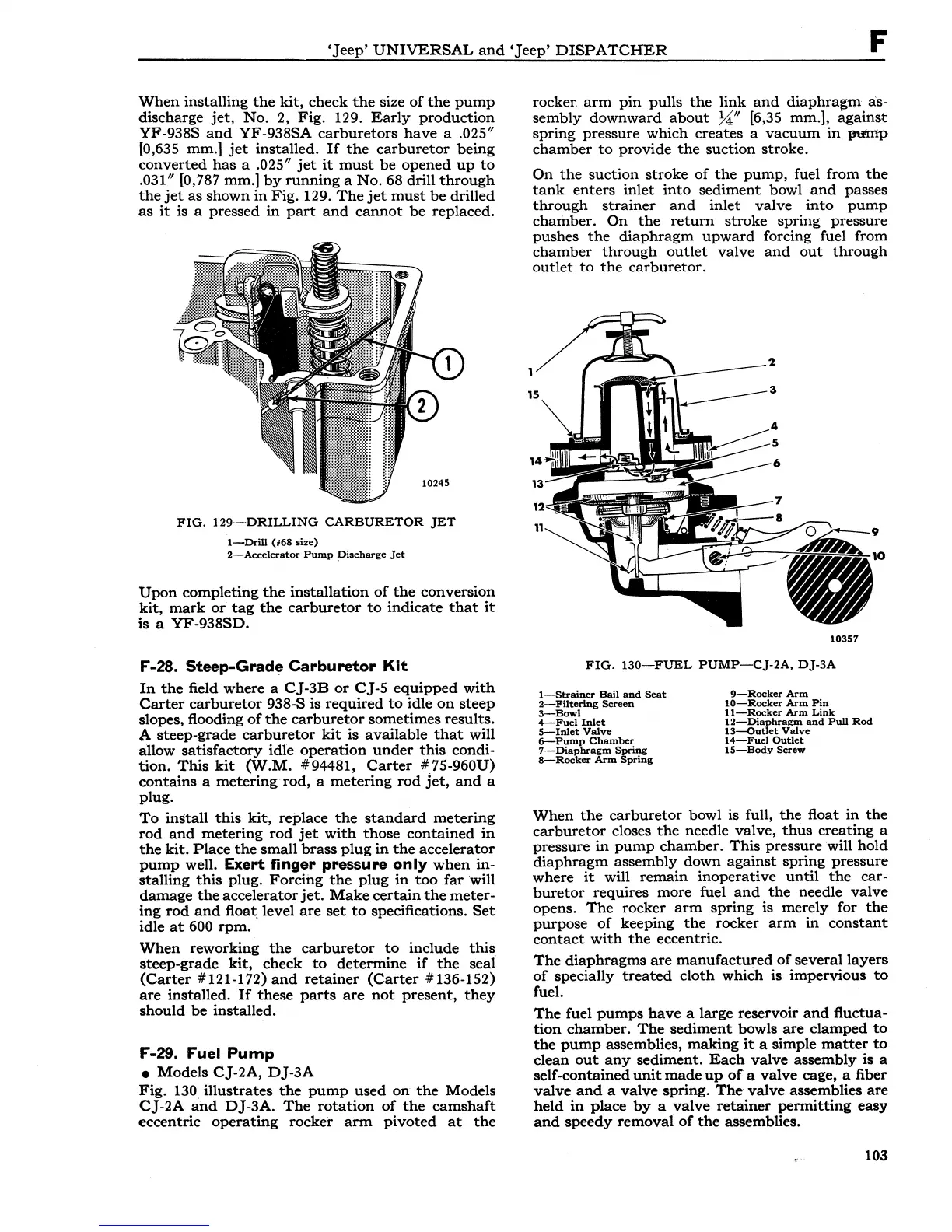
Fig. 129.
Early
production
YF-938S
and
YF
-938SA
carburetors
have
a .025"
[0,635 mm.]
jet
installed.
If
the
carburetor
being
converted
has
a .025"
jet
it
must
be
opened
up
to
.031" [0,787 mm.]
by
running
a
No.
68 drill
through
the
jet
as
shown
in
Fig. 129.
The
jet
must
be
drilled
as
it
is a pressed
in
part
and
cannot
be
replaced.
FIG.
129-DRILLING
CARBURETOR
JET
1-Drill
(#68
size)
2-Accelerator
Pump
Discharge
Jet
Upon
completing
the
installation
of
the
conversion
kit,
mark
or
tag
the
carburetor
to
indicate
that
it
is a
YF
-938SD.
F-28. Steep-Grade Carburetor Kit
In
the
field
where
a
CJ-3B
or
CJ-5
equipped
with
Carter
carburetor
938-S is
required
to
idle
on
steep
slopes, flooding
of
the
carburetor
sometimes results.
A steep-grade
carburetor
kit
is available
that
will
allow
satisfactory
idle
operation
under
this
condi-
tion.
This
kit
(W.M.
#94481,
Carter
#75-960U)
contains
a
metering
rod, a
metering
rod
jet,
and
a
plug.
To
install
this
kit,
replace
the
standard
metering
rod
and
metering
rod
jet
with
those
contained
in
the
kit.
Place
the
small
brass
plug
in
the
accelerator
pump
well. Exert finger pressure
only
when
in-
stalling
this
plug.
Forcing
the
plug
in
too
far
will
damage
the
accelerator
jet.
Make
certain
the
meter-
ing
rod
and
float, level
are
set
to
specifications.
Set
idle
at
600
rpm.
When
reworking
the
carburetor
to
include
this
steep-grade
kit,
check
to
determine
if
the
seal
(Carter
#121-172)
and
retainer
(Carter
#136-152)
are
installed.
If
these
parts
are
not
present,
they
should
be
installed.
F-29. Fuel
Pump
•
Models
CJ-2A,
DJ-3A
Fig.
130
illustrates
the
pump
used
on
the
Models
CJ-2A
and
DJ-3A.
The
rotation
of
the
camshaft
eccentric
operating
rocker
arm
pivoted
at
the
rocker
arm
pin
pulls
the
link
and
diaphra~m
as-
sembly
downward
about
X" [6,35 mm.],
against
spring pressure which creates a
vacuum
in
1!"f111p
chamber
to
provide
the
suction
stroke.
On
the
suction
stroke
of
the
pump,
fuel from
the
tank
enters
inlet
into
sediment
bowl
and
passes
through
strainer
and
inlet
valve
into
pump
chamber.
On
the
return
stroke
spring pressure
pushes
the
diaphragm
upward
forcing fuel from
chamber
through
outlet
valve
and
out
through
outlet
to
the
carburetor.
10357
FIG.
130-FUEL
PUMP-CJ-2A,
DJ-3A
l--8trainer
Bail
and
Seat
2-Filtering
Screen
3-Bowl
4-Fuel
Inlet
5-Inlet
Valve
6-Pump
Chamber
7-'-Diaphragm
Spring
B-Rocker
Arm
Spring
9-Rocker
Arm
10-Rocker
Arm
Pin
11-Rocker
Arm
Link
U~u"Je~t~:nd
Pull
Rod
14-Fuel
Outlet
15-Body
Screw
When
the
carburetor
bowl is full,
the
float
in
the
carburetor
closes
the
needle valve,
thus
creating a
pressure
in
pump
chamber.
This
pressure will
hold
diaphragm
assembly down
against
spring pressure
where
it
will
remain
inoperative
until
the
car-
buretor
requires more fuel
and
the
needle
valve
opens.
The
rocker
arm
spring
is merely for
the
purpose
of
keeping
the
rocker
arm
in
constant
contact
with
the
eccentric.
The
diaphragms
are
manufactured
of
several
layers
of
specially
treated
cloth
which is impervious
to
fuel.
The
fuel
pumps
have
a large reservoir
and
fluctua-
tion
chamber.
The
sediment
bowls
are
clamped
to
the
pump
assemblies,
making
it
a simple
matter
to
clean
out
any
sediment.
Each
valve
assembly is a
self-contained
unit
made
up
of
a valve cage, a fiber
valve
and
a
valve
spring.
The
valve
assemblies
are
held
in
place
by
a
valve
retainer
permitting
easy
and
speedy
removal
of
the
assemblies.
103