EasyManua.ls Logo

Jeep UNIVERSAL CJ-2A - Page 157

Jeep UNIVERSAL CJ-2A
281 pages
Print Icon
To Next Page IconTo Next Page
To Previous Page IconTo Previous Page
Loading...
J
CLUTCH
available
for
installation
on
these
veh
icles
when
desired.
J-3.
Clutch
Pedal
Adjustment
As t
he
clutch
facings
wear
the
free
pedal
travel
diminishes
.
Wh
en
sufficient
wear
occu
rs
to
cause
t
he
pedal
to
rest
against
the
toe
board
it
is
necessary
to
adjust
the free tr
avel.
Note:
Some
older
'Jeep'
vehicles
may
develop
side
movement
of
the
clutch
and
brake
pedals
r
esulting
from
wear
of
the
pedals,
sh
afts,
and
bushings.
On
e
way
to
compensate
for
this
wear
is
to
install
a
pedal
slack
ad
ju
ster
k
it.
Clutch
cont
rol
us
ed
on
Models
CJ
-2
A,
and
CJ
-3A
is
shown
in
Fig
. 174.
The
free
pedal
cleara
nce is
ad
justed
by
lengthenin
g
or
shortening
the
clutch
control
lever
cable.
Correct
clearance
is 1
~"
[38, 1
mm.
).
This
clearance
is
e
ssentia
l
to
dis
engage
the
clutc
h release
bearing
and
prevent
unnecessary
wear
and
possible
clutch
slippage.
Wh
en
adjusted
as
outlined
above
there
is a safe clear
ance
of
approximately
VJ
6
"
[1
,58
mm
.)
between
the
clutch
release
bearings
and
the
clutch
fingers.
To
make
this
adjust
men
t,
l
oosen
clutc
h
control
lever
cable
ad
ju
sting
yoke
l
ocknut
Fig
. 177. W
ith
a wr
ench
un
screw
the
cable,
then
tighten
the
lock-
nut.
Clut
ch
contro
l
used
on
Models
CJ-3B
,
CJ
-5,
CJ-6,
and
D J -
3A
is
shown
in
Fig.
1 77. T
he
free
peda
l
clear
ance
is
adj
ust
ed
by
lengt
h
ening
or
shortening
th
e
clutch
cont
rol
cable.
Correct
clearance
is 1"
[25,4
mm
.).
To
make
this
adjustment,
loosen lock
nut,
and
uns
crew cable
to
proper
ad
jus
tment
then
tighten
locknut.
Free
pedal
travel
is
measured
at
the
clutc
h
pedal
pad
.
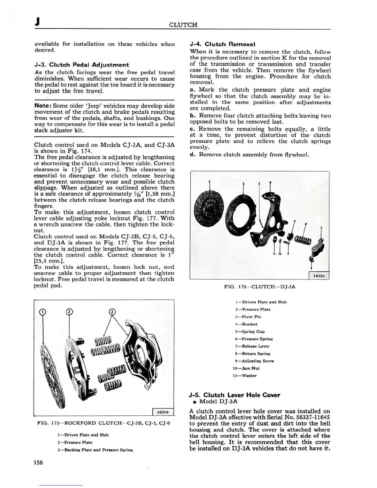
10319
FIG.
175-
ROCKFORD
CLUTCH
-
CJ-38,
CJ
-5,
CJ-6
156
! -
Driven
Plate
and
Hub
2-
Prellure
Plate
3- Bac
king
Plate
and
Preuure
Spri
ng
J-
4.
Clutch
Remova
l
Wh
en
it
is
necessary
to
remove
the
clu
tc
h, follow
the
pr
oce
dure
ou
tl
ined
in
section
K
for
the
removal
of
the
transmission
or
transmission
and
transfer
case
from
the
vehicle.
Then
remove
the
flywheel
housing
from
the
engin
e.
Pr
ocedure
for
clutch
removal.
a .
Mark
th
e
clutch
pressure
plate
and
engine
fl
ywheel
so
t
ha
t
the
clutch
assembly
may
be
in-
stalled
in
the
same
position
after
adjustments
are
completed.
b.
Remov
e
four
clutch
attaching
bolts
leaving
two
opposed
bolts
to
be
removed
last.
c .
Remov
e the
remaining
bolts
equally,
a
litt
le
at
a
time,
to
preve
nt
distortion
of
the
clutch
pressure
plate
and
to
relieve
the
clutch
sp
ring
s
evenly.
d.
Remove
clutch
assem
bly
from
flywheel.
FIG
. 1 76-
CLUTC
H-
DJ-3A
!-
Drive
n
Plate
a
nd
Hub
2- P
ressure
Plate
3-
Pivot
Pin
4-
Brncket
5-Spring
Cup
6-Pre
uure
Spring
7-
Release
Lever
8-
Return
Spring
9-
Adjusting
Screw
1
0-Jam
Nut
11-Waaher
J-5.
ClutCh L
eve
r
Ho
le
Co
v
er
•
Model
DJ
-3A
10320
A clu
tc
h
contro
l l
ever
hol
e
cover
was
installed
on
Mo
del
DJ
-
3A
effective
with
Serial
No.
56337-11645
to
prev
ent
the
entry
of
dust
and
dirt
into
the
bell
hou
sing
and
clutch.
The
cover
is
attached
where
the
clutch
cont
rol
lever
enters
the
left
side
of
the
bell
hou
sing
. It is
recommended
that
this
cover
be
installed
on
DJ
-
3A
vehicles
that
do
not
have
it.