EasyManua.ls Logo

Jeep UNIVERSAL CJ-2A - Page 210

Jeep UNIVERSAL CJ-2A
281 pages
Print Icon
To Next Page IconTo Next Page
To Previous Page IconTo Previous Page
Loading...
'Jeep'
UNIVERSAL
and
'
Jeep'
DISPATCHER
N
~
----
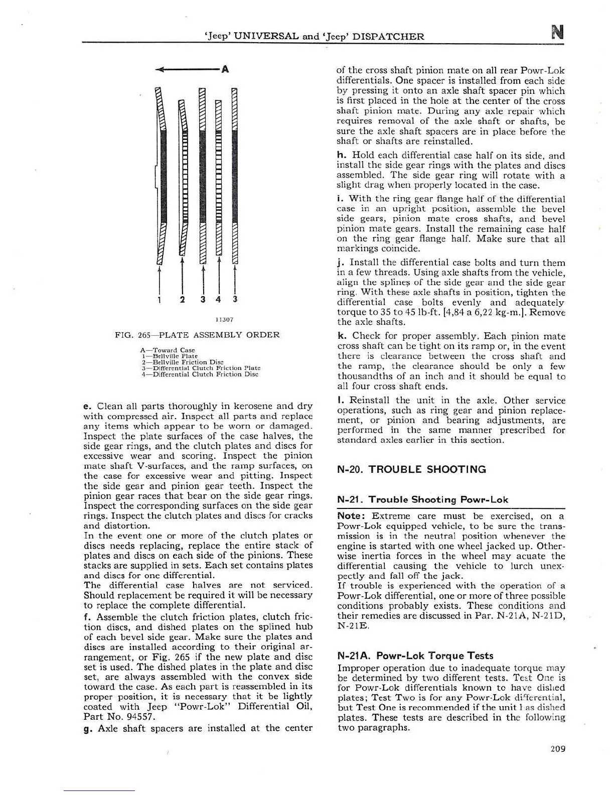
A
l 1
111
2 3 4 3
113
07
FIG.
265-
PLATE
ASSEMBLY
ORDER
A-
Towa
rd Ca
se
1-
Be
llv
i
ll
e P
late
2-
Bellv
i
ll
c
Friction
Di
sc
3-
Diff
e
rentia
l C
lu
tch Fric
ti
on
Plate
4- DifTer
cntiol
Clut
ch
Fri
c
ti
o n
Di
sc
e.
Clean
all
parts
t
horoughly
in
kerosene
and
dry
wit
h
compressed
air
.
Inspect
all
parts
and
re
place
any
i
tems
which
appea
r
to
be
worn
or
damaged.
Inspe
ct
the
plate
surfaces
of
the
case
halves,
the
s
ide
gear
ri
ngs,
and
t he
clutch
plates
and
discs
for
exces
sive
wear
and
scoring
.
Inspect
the
pinion
mate
shaft
V -
surfaces,
and
the
r
amp
surfaces,
on
the
case
for
excessive
wear
and
pitting
.
Inspect
the
side
gear
and
pinion
gear
teeth.
Inspect
the
pinion
gear
races
that
bear
on
the
side
gear
rings.
Inspect
the
corresponding
surfaces
on
the
side
gear
rings.
Inspec
t
the
clutch
plates
and
discs
for
cracks
and
distortion
.
In
the
event
one
or
more
of
the
clutch
plates
or
discs
needs
replacing,
replace
the
entire
st
ac
k
of
plates
and
discs
on
each
side
of
the
pinions
.
These
st
a
cks
are
suppli
ed
in
sets.
Each
set
contains
pl
ates
and
dis
cs for
one
differential.
The
differential
case
ha
lv
es
are
not
servic
ed
.
Should
replacemen
t
be
required
it
will be
necessary
to
replace
the
complete
differen
tia
l.
f. A
ssemble
the
clutch
fric
t
ion
plates,
clutch
fric-
tion
discs, a
nd
dished
plates
on
the
splined
hub
of
each
bevel
s
ide
gear.
Make
sure
the
plates
and
discs
are
install
ed a
ccording
to
their
ori
g
inal
ar-
rangement,
or
Fig.
265
if
t
he
new
plate
and
disc
set
is
used.
The
dished
plates
in
t
he
pl
ate
and
di
sc
set,
are
always
assembled
with
the
convex
side
toward
the
case.
As
each
par
t
is
reassembled
in
its
proper
position,
it
is neces
sary
that
it
be
lightly
coated
with
Je
ep
"
Powr-Lok
"
Differential
Oil,
Part
No
. 94557.
g. Axle
shaft
spacers
are
installed
at
the
center
of
the
cros
s
shaft
pinion
mate
on
all
rea
r P
ow
r
-Lok
diff
erent
ials
.
On
e
spacer
is
installed
from
each
side
by
pres
sin
g
it
on
to
an
axle
shaft
spacer
pin
whic
h
is
first
placed
in
the
hole
at
the
center
of
the
cross
shaft
pi
ni
on
mate.
During
any
axle
repa
ir
which
req
uir
es
removal
of
the
axle
sha
ft
or
shafts,
be
sure
the
axle
sh
aft
spacers
are
in
place
b
efore
t
he
shaft
or
sh
afts
are re
in
sta
lled .
h .
Hold
each
differe
ntial
case
half
on
i
ts
side,
and
install
the s
id
e
gear
rings
wit
h t he
plates
an
d
discs
assemb
l
ed.
The
side
gear
ring
will r
otate
with
a
sli
ght
drag
when
pro
p
er
ly l
ocated
in
the
case
.
i.
Wi
th
th
e
ring
gear
flange
half
of
the
differential
case
in
an
upright
position,
asse
mb
le
the
bevel
si
de
gears
, pini
on
mate
cro
ss
sh
afts,
and
beve
l
pinion
mate
gears.
I
nst
all
the
remaining
case
half
on
the
ring
gear
flange half. M
ake
sure
that
all
markings
coincide.
j .
Insta
ll t
he
diff
erent
i
al
case
bolts
a
nd
turn
them
in
a few t
hr
eads.
Using
axle
shafts
from
the
vehicle,
align
the
splinel'
of
the si
de
gea
r
and
the
s
ide
gea
r
ring.
Wi
th
th
ese
ax
le
shafts
in
position,
tig
h
ten the
differential
case .
bolts
even
ly
and
a
dequat
ely
torque
to
35
to
45
lb
-
ft
. [
4,84
a 6,22
kg
-m.
).
R
emo
ve
the
axle
shafts.
k.
Check
for
proper
assembly
. E
ach
pin
ion
m
ate
cross
shaft
can
be
tight
on
i
ts
ramp
or,
in
the
event
the
re
is
clea
r
ance
be
t
ween
the
cross
shaft
and
the
ramp,
the
clearance
should
be
on
ly a f
ew
thousandths
of
an
i
nch
and
it
should
be
e
qu
al
to
all
four
cross
shaft
end
s.
I.
R e
in
stall
the
unit
in
the
axle.
Other
service
operatio
n
s,
suc
h
as
ring
gear
an
d
pinion
replace-
ment,
or
pinion
and
bearing
adjustments,
are
pe
rf
ormed
in
the
same
m
anne
r
prescribed
for
standa
rd
ax
les
ea
rli
er
in
t
his
section.
N-
20.
TROUBLE
SHOOTING
N-
21.
Troub
le Shoo
tin
g Pow
r-L
ok
Note
:
Extr
eme
care
must
be
exercised,
on
a
P
ow
r-
Lok
e
quipp
ed
vehicle,
to
be
sure
the
trans-
mission
is
in
t
he
neutral
position
whenever
the
engine
is
started
with
on
e
wh
ee
l
jac
ked
up
. O
ther-
wise
inertia
forces
in
the
wheel
may
acuate
the
diff
ere
ntial
caus
ing
the
ve
hicle
to
lu
r
ch
unex·
pectly
and
fall
off
the
jack.
If
trouble
is
expe
rie
nced
with
the
ope
r
at
i
on
of a
Po
wr-
Lok
differential,
one
or
more
of
t
hr
ee
possible
cond
i
tions
probably
exists
.
Thes
e
cond
it
ions and
their
remedies
are
discuss
ed
in
Par.
N-21A, N
-2
1
D,
N
-2
1E.
N-2
1A
. Po
wr
-L
ok
Torq
ue T
es
ts
Impr
oper
operation
due
to
inadequate
torqu
e
ma
y
be
determined
by
two
different
tests
.
T
e
~ t
O
ne
is
for
Powr
-L
ok
differentials
known
to
ha
ve
dis
h
ed
plates;
Test
Two
is for a
ny
Powr
-Lok dilfe
ren
tial,
but
T
es
t
One
is
re
comm
ended
if
the
u
ni
t I as di
she
d
plates
.
These
tests
are
described
in
th
e follow
in
g
two
par
ag
r
ap
hs
.
209