EasyManua.ls Logo

Jeep UNIVERSAL CJ-2A - Page 32

Jeep UNIVERSAL CJ-2A
281 pages
Print Icon
To Next Page IconTo Next Page
To Previous Page IconTo Previous Page
Loading...
'Jeep'
UNIVERSAL
and
'Jeep'
DISPATCHER
D
Piston
and
connecting
rod
assemblies
may
be
re-
moved
for
repair
with
the
engine
in
the
vehicle
after
draining
the
cooling
system,
removing
the
oil
pan
and
the
cylinder
head,
and
reaming
the
ridges
as
previously
described.
D-18. Remove
Timing
Gear
Cover
Remove
the
bolts,
nuts,
and
lockwashers
that
at-
tach
the
timing
gear
cover
(timing
chain
cover
on
early
models)
to
the
engine.
Remove
the
cover,
timing
pointer,
and
cover
gasket.
Discard
the
gasket.
Remove
the
crankshaft
oil seal.
Remove
the
oil slinger
and
spacer
from
the
crankshaft.
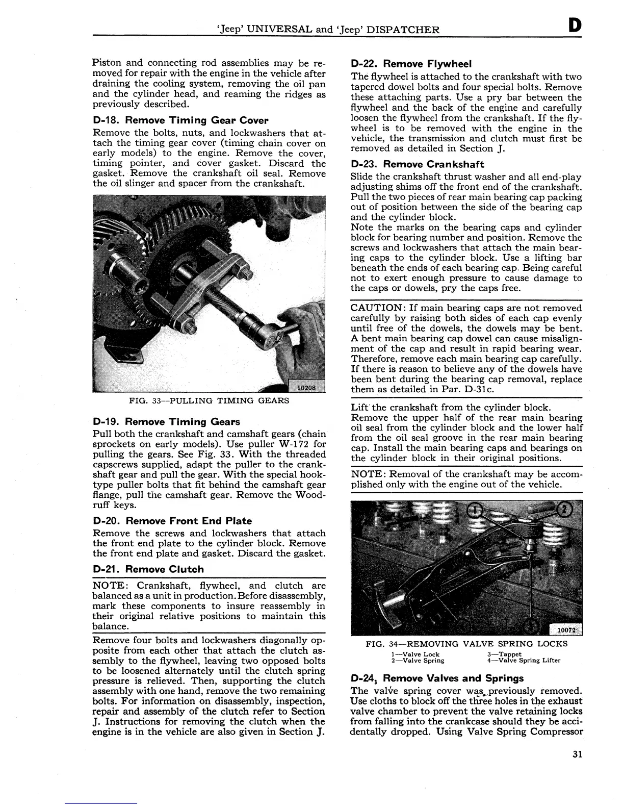
FIG.
33-PULLING
TIMING
GEARS
D-19. Remove
Timing
Gears
Pull
both
the
crankshaft
and
camshaft
gears
(chain
sprockets
on
early
models).
Use
puller
W-172 for
pulling
the
gears. See
Fig.
33.
With
the
threaded
capscrews supplied,
adapt
the
puller
to
the
crank-
shaft
gear
and
pull
the
gear.
With
the
special hook-
type
puller
bolts
that
fit
behind
the
camshaft
gear
flange,
pull
the
camshaft
gear.
Remove
the
Wood-
ruff
keys.
D-20. Remove
Front
End
Plate
Remove
the
screws
and
lockwashers
that
attach
the
front
end
plate
to
the
cylinder
block.
Remove
the
front
end
plate
and
gasket.
Discard
the
gasket.
D-21. Remove
Clutch
NOTE:
Crankshaft,
flywheel,
and
clutch
are
balanced
as
a
unit
in
production.
Before disassembly,
mark
these
components
to
insure
reassembly
in
their
original
relative
positions
to
maintain
this
balance.
Remove
four
bolts
and
lockwashers
diagonally
op-
posite
from
each
other
that
attach
the
clutch
as-
sembly
to
the
flywheel,
leaving
two
opposed
bolts
to
be
loosened
alternately
until
the
clutch
spring
pressure
is relieved.
Then,
supporting
the
clutch
assembly
with
one
hand,
remove
the
two
remaining
bolts.
For
information
on
disassembly,
inspection,
repair
and
assembly
of
the
clutch
refer
to
Section
J.
Instructions
for
removing
the
clutch
when
the
engine is
in
the
vehicle
are
also given
in
Section
J.
D-22. Remove Flywheel
The
flywheel is
attached
to
the
crankshaft
with
two
tapered
dowel
bolts
and
four special bolts.
Remove
these
attaching
parts.
Use a
pry
bar
between
the
flywheel
and
the
back
of
the
engine
and
carefully
loosen
the
flywheel
from
the
crankshaft.
If
the
fly-
wheel is
to
be
removed
with
the
engine
in
the
vehicle,
the
transmission
and
clutch
must
first
be
removed
as
detailed
in
Section
J.
D-23. Remove
Crankshaft
Slide
the
crankshaft
thrust
washer
and
all
end-play
adjusting
shims
off
the
front
end
of
the
crankshaft.
Pull
the
two
pieces
of
rear
main
bearing
cap
packing
out
of
position
between
the
side
of
the
bearing
cap
and
the
cylinder
block.
Note
the
marks
on
the
bearing
caps
and
cylinder
block
for
bearing
number
and
position.
Remove
the
screws
and
lockwashers
that
attach
the
main
bear-
ing
caps
to
the
cylinder
block.
Use
a lifting
bar
beneath
the
ends
of
each
bearing
cap.
Being
careful
not
to
exert
enough
pressure
to
cause
damage
to
the
caps
or
dowels,
pry
the
caps
free.
CAUTION:
If
main
bearing
caps
are
not
removed
carefully
by
raising
both
sides
of
each
cap
evenly
until
free
of
the
dowels,
the
dowels
may
be
bent.
A
bent
main
bearing
cap
dowel
can
cause misalign-
ment
of
the
cap
and
result
in
rapid
bearing
wear.
Therefore,
remove
each
main
bearing
cap
carefully.
If
there
is
reason
to
believe
any
of
the
dowels
have
been
bent
during
the
bearing
cap
removal, replace
them
as
detailed
in
Par.
D-31 c.
Lift'
the
crankshaft
from
the
cylinder
block.
Remove
the
upper
half
of
the
rear
main
bearing
oil seal
from
the
cylinder
block
and
the
lower
half
from
the
oil seal groove
in
the
rear
main
bearing
cap.
Install
the
main
bearing
caps
and
bearings
on
the
cylinder
block
in
their
original positions.
NOTE:
Removal
of
the
crankshaft
may
be
accom-
plished
only
with
the
engine
out
of
the
vehicle.
FIG.
34-REMOVING
VALVE
SPRING
LOCKS
!-Valve
Lock
2-Valve
Spring
3-Tappet
4-Valve
Spring
Lifter
D-24
1
Remove Valves
and
Springs
The
valve
spring
cover
w~~.,._previously
removed.
Use
cloths
to
block
off
the
three
holes
in
the
exhaust
valve
chamber
to
prevent
the
valve
retaining
locks
from
falling
into
the
crankcase
should
they
be
acci-
dentally
dropped.
Using
Valve
Spring
Compressor
31