EasyManua.ls Logo

Jeep UNIVERSAL CJ-2A - Page 45

Jeep UNIVERSAL CJ-2A
281 pages
Print Icon
To Next Page IconTo Next Page
To Previous Page IconTo Previous Page
Loading...
D
L4-134
ENGINE
on
later
models,
and
20 lb. [1,406 kg-cm2)
at
2000
rpm.
(32
mph.
[51
kph.]).
NOTE:
Safe
minimum
pressure
of
the
earlier
type
pump
is
10
psi. [0,7 kg-cm2)
at
idle
speed.
Normal
gauge
reading
will be. 50
at
30
mph.
[48
km-hr.]
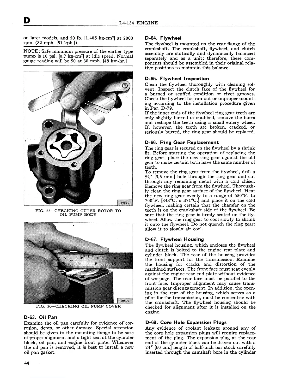
FIG.
SS~CHECKING
OUTER
ROTOR
TO
OIL
PUMP
BODY
FIG.
56~CHECKING
OIL
PUMP
COVER
D-63. Oil
Pan
Examine
the
oil
pan
carefully
for
evidence
of'
cor-
rosion,
dents,
or
other
damage.
Special
attention
should
be
given
to
the
mounting
flange
to
be
sure
of
proper
alignment
and
a
tight
seal
at
the
cylinder
block,
oil
pan,
and
engine
front
plate.
Whenever
the
oil
pan
is
removed,
it
is
best
to
install
a
new
oil
pan
gasket.
·
44
D-64.
Flywheel
The
flywheel is
mounted
on
the
rear
flange
of
the
crankshaft.
The
crankshaft,
flywheel,
and
clutch
assembly
are
statically
and
dynamically
balanced
separately
and
as
a
unit;
therefore,
these
com-
ponents
should
be
assembled
in
their
original
rela-
tive
positions
to
maintain
this
balance.
D-65.
Flywheel
Inspection
Clean
the
flywheel
thoroughly
with
cleaning
sol-
vent.
Inspect
the
clutch
face
of
the
flywheel
for
a
burned
or
scuffed
condition
or
rivet
grooves.
Check
the
flywheel
for
run-out
or
improper
mount-
ing
according
to
the
installation
procedure
given
in
Par.
D-79.
If
the
inner
ends
of
the
flywheel
ring
gear
teeth
are
only
slightly
burred
or
snubbed,
remove
the
burrs
and
reshape
the
teeth
using
a
small
emery
wheel.
If,
however,
the
teeth
are
broken,
cracked,
or
seriously
burred,
the
ring
gear
should
be
replaced.
D-66. Ring
Gear
Replacement
The
ring
gear
is
secured
on
the
flywheel
by
a
shrink
fit.
Before
starting
the
operation
of
replacing
the
ring
gear,
place
the
new
ring
gear
against
the
old
gear
to
make
certain
both
have
the
same
number
of
teeth.
To
remove
the
ring
gear
from
the
flywheel, drill a
%"
[9,5
mm.]
hole
through
the
ring
gear
and
cut
through
any
remaining
metal
with
a
cold
chisel.
Remove
the
ring
gear
from
the
flywheel.
Thorough-
ly
clean
the
ring
gear
surface
of
the
flywheel.
Heat
the
new
ring
gear
evenly
to
a
range
of
650°F.
to
700°F. [343°C. a 371 °C.]
and
place
it
on
the
cold
flywheel,
making
certain
that
the
chamfer
on
the
teeth
is
on
the
crankshaft
side
of
the
flywheel.
Be
sure
that
the
ring
gear
is
firmly
seated
on
the
fly-
wheel. Allow
the
ring
gear
to
cool
slowly
to
shrink
it
onto
the
flywheel.
Do
not
quench
the
ring
gear;
allow
it
to
slowly
air
cool.
D-67.
Flywheel
Housing
The
flywheel
housing,
which
encloses
the
flywheel
and
clutch
is
bolted
to
the
engine
rear
plate
and
cylinder
block.
The
rear
of
the
housing
provides
the
front
support
for
the
transmission.
Examine
the
housing
for
cracks
and
distortion
of
the
machined
surfaces.
The
front
face
must
seat
evenly
against
the
engine
rear
end
plate
without
evidence
of
warpage.
The
rear
face
must
be
parallel
to
the
front
face.
Improper
alignment
may
cause
trans-
mission
gear
disengagement.
In
addition,
the
open-
ing
in
the
rear
of
the
housing,
which
serves
as
a
pilot
for
the
transmission,
must
be
concentric
with
the
crankshaft.
The
flywheel
housing
should
be
checked
for
alignment
after
it
is
installed
on
the
engine.
D-68.
Core
Hole
Expansion
Plugs
Any
evidence
of
coolant
leakage
around
any
of
the
core
hole
expansion
plugs
will
require
replace-
ment
of
the
plug.
The
expansion
plug
at
the
rear
end
of
the
cylinder
block
can
be
driven
out
with
a
24"
[60 em.]
length
of
half-inch
bar
stock
carefully
inserted
through
the
camshaft
bore
in
the
cylinder