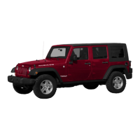
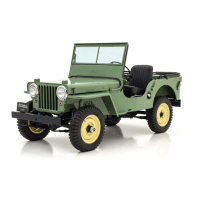
'Jeep'
UNIVERSAL
and
'Jeep'
DISPATCHER
E-114. F4-134 ENGINE SPECIFIC.ATIONS
MODEL:
ENGINE:
Type
...............................
.
Number
of
Cylinders
.................
.
Bore
................................
.
Stroke
..............................
.
Piston
Displacement
..................
.
Bore
Spacing
(center
to
center):
1
and
2, 3
and
4
....................
.
2
and
3
...........................
.
Firing
Order
.........................
.
Compression
Ratio:
Standard
..........................
.
Optional
..........................
.
Compression
Pressure
.................
.
Number
of
Mounting
Points:
Front
.............................
.
Rear
..............................
.
Horsepower
(
SAE)
...................
.
Horsepower
(Max
Brake)
..........
."
..
Maximum
Torque
@ 2000
rpm
........
.
Idle
Speed
...........................
.
Governor
Speed
(optional):
Velocity
...........................
.
Centrifugal.
. . . . . . . . . . . . . . . .
......
.
PISTONS:
Material.
...........................
.
Description
..........................
.
Length
..............................
.
Diameter
(near
bottom
of
skirt)
........
.
Weight
..............................
.
Clearance
Limits:
Piston-
To-Cylinder
Bore
........
.
Ring
Groove
Depth:
No.
1
and
2
Ring
...................
.
No.
3
Ring
........................
.
Ring
Groove
Width:
No.1
Ring
.........
,
..............
.
No.
2
Ring
........................
.
No.3
Ring
........................
.
Piston
Pin
Hole
Bore
.................
.
Cylinder
Bore
-
Standard
............
.
-
max.
out
of
round
...............
.
-max.
taper
.......................
.
-
max
..
rebore
.....................
.
PISTON
RINGS:
Function:
No.
1
and
2,
...
·.
.
...............
.
No.3
.............................
.
Material:
No.1
.............................
.
No.
2
and
3
.......................
.
Width:
No.
1
and
2
.......................
.
No.3
.............................
.
Gap
<std.
to
.oo9
cyl.
Bore)
............
1
Thickness:
No.1
and
No.2
Rings
..............
.
No.
3
Ring
........................
.
Side
Clearance
in
Groove:
No.
1
Ring
.....................
.
No.
2
Ring
....................
.
No.3
Ring
........
.
PISTON
PINS:
Material
......
.
Length
.........................
.
Diameter
......................
.
Type
...............................
.
Clearance
in
Piston
(selective
fit)
.......
.
CJ-3B,
CJ-5,
CJ-6
F-Head
4
3Ys"
4%"
134.2
cu.
in.
3.437"
4.938"
1-3-4-2
7.4:1
6.9:1
120
to
130
psi.
2
1
15.63
75 @ 4000
rpm.
114
lb-ft.
600
rpm
2200
to
3200
rpm.
1000
to
2600
rpm.
Aluminum
Alloy
Cam
Ground,
T
-slot,
Tin
Plated
3%;"
3.1225"
to
3.1245"
13.5
oz.
Selective
Feeler
Fit
.1593"
to
.1655"
.
1693"
to
.1755"
.0955"
to
.0965"
.095"
to
.096"
.1875"
to
.1885"
.760"
to
.770"
3.125"
to
3.127"
.005"
.
005"
.040"
Compression
Oil
Cast
Iron,
Chrome-plated
Face
Cast
Iron
%"
lJ.W"
.007"
to
.045"
.134"
to
.144"
.115"
to
.125"
.002"
to
.004"
.
0015"
to
.0035"
.
001"
to
.0025"
SAE
1016
Steel
2.781
11
.
8119"
to
.8121"
Locked
in
Rod
.0001"
to
.0003"
METRIC
79,375
mm.
111,12
mm.
2199 emS
8,729
em.
12,542
em.
8,4
a 9,2 kg-cm2
15,77
kg-m.
9,525
em.
7,9311 a 7,9362
em.
382,7
gr.
4,046
a 4,203
mm
.
4,300
a 4,457
mm.
2,4257 a 2,4511
mm.
2,413 a 2,438
mm.
4,7625 a 4,7879
mm.
19,304 a 19,558
mm.
7,9375 a 7,9425
em.
0,1270
mm
.
0,1270
mm.
1,0160
mm.
2,38
mm.
4,76
mm.
0,178
a 1,143
mm.
0,3403 a
0,3657
mm.
0,2821 a 0,3175
mm.
0,051 a 0,102
mm
.
0,038
a
0,088
mm
.
0,025
a 0,063
mm.
70,637
mm.
20,6223
mm
.
0,0025
a
0,0076
mm.
E
89
 Loading...