Internal error
The dosing pump carries out a self-check, which switches off the pump if no stroke has been carried out
two seconds after motor start-up (e.g. if back pressure is too high) or if the proximity switch (stroke sensor)
does not respond (display E-2). The alarm is reset by pulling out the mains plug.
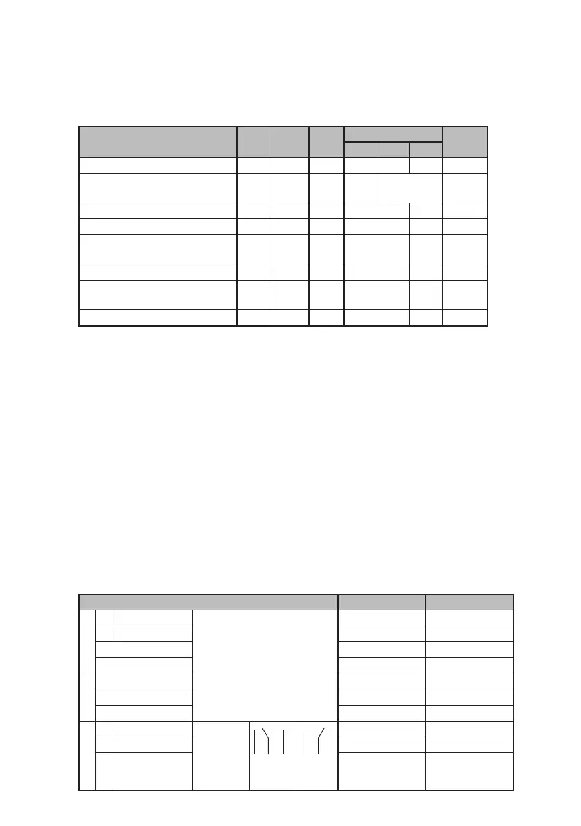
The functions of the LEDs and built-in warning alarm relay are shown in the following table:
Condition LED 1
ON
LED 2
Extern
LED
Alarm
Warning alarm relay Display
R0 RW R1
Power supply absent closed -
Dosing pump running
closed Number
of strokes
Dosing pump off (by ON/OFF switch) closed OFF
Dosing pump off (by external contact)
closed OFF
Level pre-alarm
*) flashes closed Number
of strokes
Level main alarm
*)
closed E - L
Dosing pump fault (proximity switch,
stroke sensor)
*)
closed E - 2
Dosing pump fault (current < 4 mA)
closed E - I
*) LED 2 is lit in operating modes 1.1 - 1.64; 0...20 mA and 4... 20 mA
8.6 Other settings
8.6.1 Max. number of strokes
Press and hold the "Mode" and "I/O" keys while applying the voltage, and set the maximum pump stroke
frequency using keys ▼ and ▲. When the "Mode" key is released, normal operation starts.
8.6.2 Warning alarm relay connection
Relay not activated in case of fault or OFF: When voltage is applied, press and hold "Mode" and ▲ keys.
Display: "RE0". Relay activated in case of fault or OFF: When voltage is applied, press and hold "Mode" and
▼ keys. Display: "RE1".
8.7 Factory setting
• The initial status of MEMDOS DX is "OFF".
• Depending on the technical specifications, the maximum stroke frequency is preset (see section 5).
• In case of a fault or "OFF", the warning alarm relay is not activated.
8.8 Connections and cable assignments
MEMDOS DX control unit Standard version CSA version
l
L1 RUN Motor BR (brown) BK (black)
L2 STOP BK (black) RD (red)
N BU (blue) or GY (grey) WH (white)
PE GN/YE (green/yellow) GN/YE (green/yellow)
k
L Power supply
230 V AC, 50/60 Hz
or 120 V AC, 50/60 Hz
BR (brown) BK (black)
N BU (blue) or GY (grey) WH (white)
PE GN/YE (green/yellow) GN/YE (green/yellow)
m
R0 Break contact Warning
alarm relay
(1.5 m cable)
R0 RW R1
Fault
R0 RW R1
Operation
BR (brown) RD (red)
Rw Changeover contact BU (blue) or GY (grey) WH (white)
R1 Make contact BK (black) BK (black)
26 | Operation & Maintenance Instructions | Operation