15. External vent (optional)
Functional description of vent motors
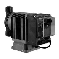
The fan cowl and fan blade of the drive motor are removed and replaced by the extended fan cowl with
integrated fan. The fan has a direct mains connection, and therefore delivers the maximum quantity of
cool air to protect the motor against overheating at all speeds. Separate fans can be operated over a wide
voltage range, according to the technical data below. They can be connected to three-phase or alternating
current power supply, if connected according to the instructions. For single-phase operation, an operating
capacitor is included in the terminal box (see electrical wiring diagram). The fan motors work according to
the direction of rotation. The air flow must be directed towards the motor.
Special versions available
• Extended fan cowl (for operation with tachogenerator or motor brake)
• Different mounting bracket
• Different fan cowl diameter
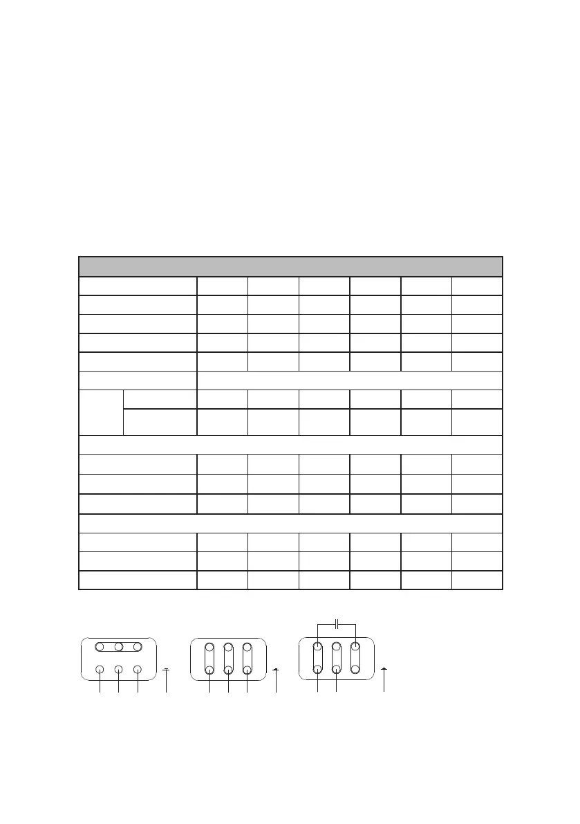
Technical Data
Motor size 63 71 80 90 100 112
Air flow rate m3/h 47 60 88 169 208 295
Power consumption W 27 30 28,5 86 86 84,5
Speed at 50 Hz (rpm) 2910 2870 2790 2880 2830 2770
Sound pressure level dB(A) 47 51 55 58 59 61
Protection class IP 66
Dimen-
sions
(mm)
Height 185 190 195 205 210 215
Diameter 126 143 160 176 196 220
Nominal motor current (A)
3~, 200...290 V, Delta 0.092 0.095 0.090 0.28 0.27 0.27
3~, 346...500 V, Y 0.06 0.06 0.05 0.06 0.06 0.06
1~, 230 V 0.075 0.081 0.090 0.19 0.21 0.23
Part No.
Motor supplier ATB 47000200 47000201 47000202 47000203 47000204 47000205
Motor supplier VEM - 47000101 47000100 - - -
Motor supplier Siemens - - 47000303 - - -
Electrical wiring diagram
L1 N PE
W2 U2 V2
U1 V1 W1
W2 U2 V2
U1 V1 W1
W2 U2 V2
U1 V1 W1
L1 L2 L3 PE L1 L2 L3 PE
L1 N PE
W2 U2 V2
U1 V1 W1
W2 U2 V2
U1 V1 W1
W2 U2 V2
U1 V1 W1
L1 L2 L3 PE
W2 U2 V2
U1 V1 W1
3~ Y-connection 3~ delta connection 1~ Steinmetz connection
External vent | Operation & Maintenance Instructions | 43