27
LATHE CONTROLS
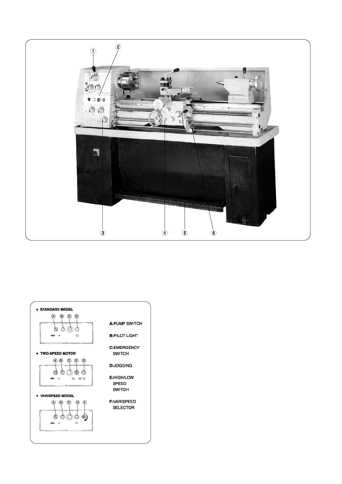
(See Fig. 8)
1. Spindle speed select levers.
2. Control panel.
3. Gearbox, threads and feed.
4. Apron, sliding & surfacing feeds
5. Footbrake.
6. Spindle rotation control lever
CONTROL PANEL (See Fig.9)
Except the lathe isolator switch, all the electrical controls are
fitted into front face between headstock and gearbox. The control
knobs & button switches functions as bellows:
1. The BLACK select knob--A for coolant pump switch ON/OFF.
2. The WHITE pilot lamp--B glows to show the main supply ON.
3. The RED mushroom-head button--C to stop all the electrical
supply.
4. The GREEN push button--D to press for spindle jogging.
5. The BLACK select knob--E for two speed motor High/Low
selection.
6. The BLACK turning knob--F for spindle speed control on
Varispeed model.
NOTE: The speed meter reflects the main spindle speed, which
is controlled by the turning knob on varispeed model.
Fig.8
Fig.9