7
Assembly
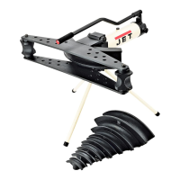
Referring to Figure 1:
1. Screw three tripod pole bases (M) onto three
tripod poles (L).
2. Screw tripod poles (M) into the tripod seat (D).
For steps 3 – 13 refer to Figure 4.
3. Pull the knob (D
1
, Fig. 3) on the tripod seat and
4. Insert the support assembly (F) onto the tripod
seat (D) by first pulling out the knob (D
1
, Fig. 3)
on the tripod seat (D). When the knob is
released, the support assembly will be secured
to the tripod seat.
5. Screw four double-ended threaded studs (M)
(short-threaded end) into bottom of the housing
base (C
1
) of the hydraulic pump unit.
6. Place the hydraulic pump unit (C) onto the
lower wing plate such that the studs protrude
through the bottom of the wing plate.
Note: The alignment holes in the wing plate
and pump unit must line up. If not, flip the wing
plate over.
7. With the assistance of a second person, lift the
hydraulic pump unit (C) and lower wing plate
(J) as a unit and place it on top of the support
assembly (F).
The studs (M) should protrude through the
bottom of the support assembly plate (F) and
the spring pin should fit into the alignment
holes of the wing plate (J) and pump unit (C).
8. Secure the pump unit (C) and wing plate (J) to
the support assembly (F) with four each M12
lock washers (N) and M12 hex nuts (O).
Tighten with a 7/8" wrench.
9. Mount swaging blocks (E) onto the end-holes
of the wing plate (J). These will be adjusted as
required later.
10. Place the upper wing plate (H) onto the pump
unit (C) and swaging blocks (E).
11. Insert hinge pin (G) though the upper wing
plate and pump unit hinge holes and secure the
hinge pin with cotter pin (R).
12. Insert the handle (K) into the handle cap (C
2
)
on the pump unit.
13. Remove the factory installed oil plug (P) and
replace with the vented oil plug (P) and rubber
O-ring (Q) from the hardware bag.
Important: Failure to replace the oil plug will
cause improper operation.
Assembly is complete and the pipe bender is ready
for use.
L
M
D
D
1
Figure 3
Figure 4