6
Fig 2
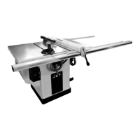
Mounting rip fence support bar
Mount the rip fence support bar (Y, Fig
3) to the front of the saw table and
right table extension.
Fig 3
Mount the scale carrier (W).
Mounting rip fence
Mount the rip fence to the rip fence
support bar.
Fig 4
The rip fence must be guided parallel
to the table surface. Adjust the round
bar (Y) up-down as needed.
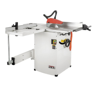
Mounting sliding table:
With the help of another person, lift
the sliding table carefully to its place
and attach (see Fig 5,6, 7 and 8).
Fig 5
Fig 6
Fig 7
Fig 8
Attach the sliding table support legs.
Sliding Table Adjustment:
The sliding table is adjusted ex works.
The sliding table must be aligned to
run parallel to the sawblade
The table surface must be 0,1 - 0,4
mm higher than the machine table.
Use rip fence profile to check (Fig 9).
Fig 9
Adjustment:
The sliding table guide assembly can
be adjusted up-down and parallel to
the sawblade.
Use the grub screws (A & B) to adjust.
Mounting telescopic arm:
Insert the beam (S, Fig 10, Fig 11) into
the telescopic arm
 Loading...