Fig 8
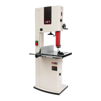
Install fence assembly and adjust:
Slide fence body (A, Fig 9) onto guide rail and move fence
body to right of blade.
Install fence profile (B) and tighten with two knobs (A1).
Slide fence against edge of mitre slot, and tighten handle
(A2). The fence should align parallel to mitre slot.
If adjustment is needed, loosen and rotate hex nuts on guide
rail studs (A3) as needed.
Tighten nuts.
Fig 9
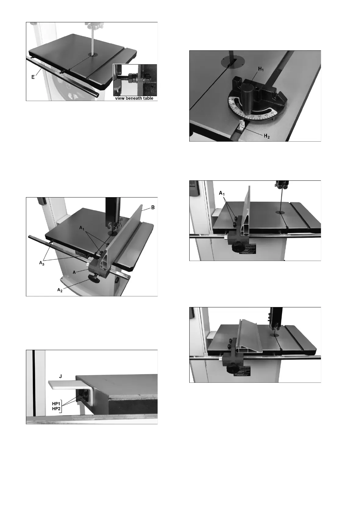
Install table bracket (JWBS-20 only):
Install bracket (J, Fig 10) on left side of table.
Level with surface of table and tighten screws.
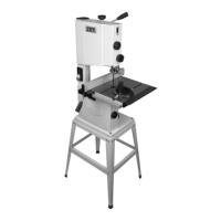
Fig 10
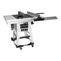
Install mitre gauge:
Slide mitre gauge into table slot.
Use a square to verify that mitre gauge face is square to the
table slot (=square to the fence profile).
If mitre gauge is not square, loosen lock knob (H1, Fig 11) and
adjust to proper setting.
If pointer is not at 90 degrees, loosen screw (H2) to adjust.
Fig 11
Fence aluminium profile adjustments:
Loosen knobs (A1, Fig 12) to adjust the aluminium fence
profile.
Fig 12: vertical
The fence profile can be installed in two positions, vertically
(Fig 12) or horizontally (Fig 13).
Horizontal position is useful for smaller workpieces, for
narrow shallow cuts.
Fig 13: horizontal
Fence fine adjustment:
Loosen fence lock knob (A, Fig 14).
Loosen knob (B).
 Loading...