15
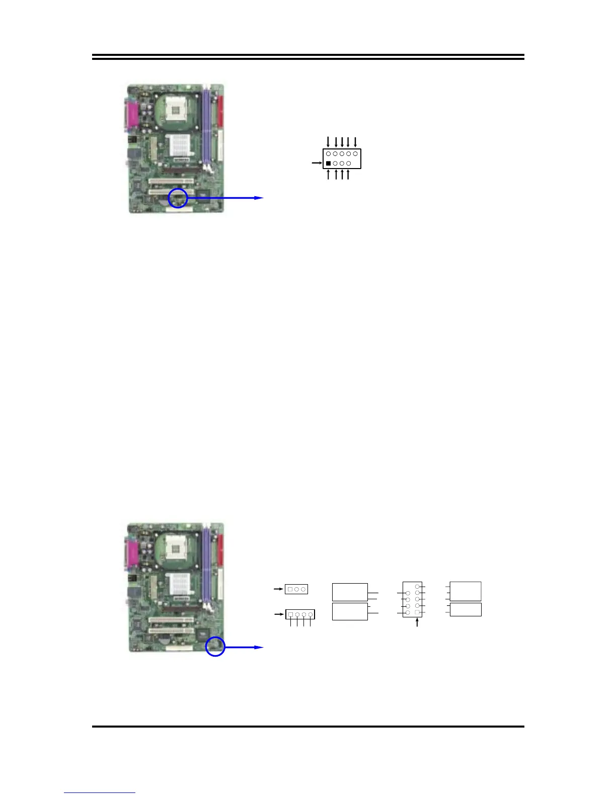
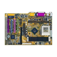
USB Port Headers
Pin 1
USB2
VCC
-DATA
GND
+DATA
VCC
OC
-DATA
GND
+DATA
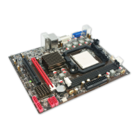
(3) IDE Activity LED: HD LED
This connector connects to the hard disk activity indicator light on the case.
(4) Reset switch lead: RESET
This 2-pin connector connects to the case-mounted reset switch for rebooting your
computer without having to turn off your power switch. This is a preferred method of
rebooting in order to prolong the lift of the system’s power supply. See the figure
below.
(5) Speaker connector: SPEAK
This 4-pin connector connects to the case-mounted speaker. See the figure below.
(6) Power LED: PWR LED
The Power LED is light on while the system power is on. Connect the Power LED
from the system case to this pin.
(7) Power switch: PWR BTN
This 2-pin connector connects to the case-mounted power switch to power ON/OFF the
system.
System Case Connections
SPEAK
SPKR
GND
NC
VCC5
Pin 1
FP
Pin 1
HDLED
RESET
VCC5
GND
HDDLED
RSTSW
NC
VCC5
POWER LED
PWRBTN
PWRBTN
POWERLED
GND
PWRLED
Pin 1