EasyManua.ls Logo

JFL Alarmes SMARTCLOUD 18 - User Manual

JFL Alarmes SMARTCLOUD 18
16 pages
Print Icon
To Next Page IconTo Next Page
Loading...
www.jfl.com.br
User
Manual
JFL
SMARTCLOUD 18
ALARM CENTRAL
Congratulations,
You have just acquired a product with JFL Alarmes quality, produced in Brazil with the highest
manufacturing technology. This manual shows all the functions of the equipment.
Question and Answer IconNeed help?

Do you have a question about the JFL Alarmes SMARTCLOUD 18 and is the answer not in the manual?

Summary

Front Panel Overview

Rede;Bateria LED Status

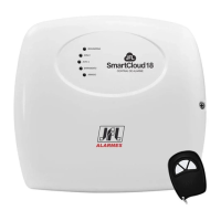
Indicates the power supply status of the device, showing AC or battery connection.

Zone 1 and Zone 2 LED Status

Indicates the current state of zones 1 and 2, such as disabled, closed, or triggered.

Bus Zone LED Status

Indicates the state of bus zones, showing open sensors or zone triggering.

Armado LED Status

Indicates whether the central unit is activated or armed.

Programming Wireless Sensors and Remote Controls

Programming Bus Sensors

Conventional Programming Method

Programs bus sensors using the central unit's programar button and remote control.

Serial Programming Method

Programs bus sensors using the Cloud Line programmer software.

Arming and Disarming the Central Unit

Enabling and Disabling Divided Mode

Enabling and Disabling Triggering Modes

Panic Function by Remote Control

Programming Mode Operations

Automatic Rearming Configuration

Arm;Disarm Beep Programming

Siren Trigger Time Configuration

Automatic Arming for Lack of Movement

Zone Programming Options

Central Unit Reset Procedures

Installation Guidelines

Technical Specifications

Device Components Identification

433.92 MHz Receiver Antenna

Receives wireless signals for sensors and remote controls.

APRENDER Button

Button used for programming wireless sensors and remote controls.

PROGRAMAR Button

Button for programming the central unit and bus devices.

AC Transformer Input

Connection point for the 12 VAC transformer.

Battery Input

Connector for a 12V / 7A battery.

Positive Battery Output

Positive terminal output for powering accessories.

PGM Auxiliary Output

Auxiliary output for dry contact, normally open.

VDC Output for Accessories

DC output for powering alarm accessories, capacity 0.2A.

SIR Siren Output

Output for triggering a piezoelectric siren.

Zone Inputs Z1 and Z2

Inputs for connecting wired sensors.

LED Indicator Output

LED output for indicating armed or disarmed status.

ON Input for Arming;Disarming

Input for arming/disarming the central unit via a negative pulse.

Bus Input (+;-)

Input terminal for connecting bus sensors.

ETH Connector for Ethernet Module

Input for connecting the ME-04 Ethernet module.

PGM Module Input

Input for connecting the MPG4 PGM module.

Connection Schemes

Connecting with Cloud Line Programmer Software

Interconnection with Ethernet Module

Access via Mobile Application

Interconnection with JFL Energizer

Interconnection of PGM Module

Important Precautions

Product Warranty Information

JFL Alarmes SMARTCLOUD 18 Specifications

General IconGeneral
BrandJFL Alarmes
ModelSMARTCLOUD 18
CategorySecurity System
LanguageEnglish