Insulation Equipment + Supply 26 InsulationEquipmentSupply.com
6.3.1 Disassembling the black and the white material booster pumps
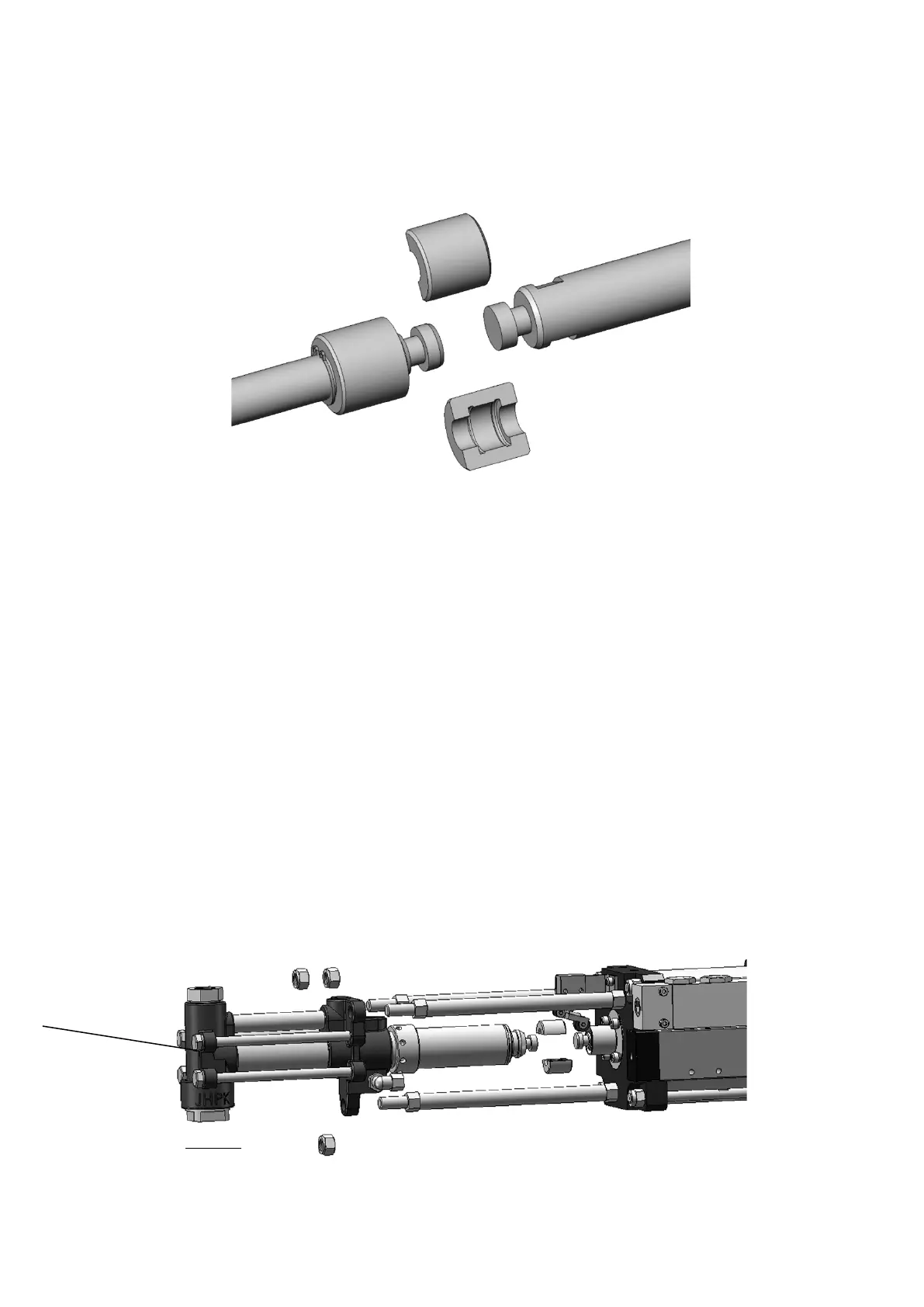
The power between the black and the white booster pumps and the cylinder shaft is transmitted by coupler
assembly, which has a construction as shown in Figure (16).
Figure (16)
Two half-cylinders with internal recess may engage tightly with the shaft end boss. The positioning sleeve of
the coupling encompasses the coupling, connects and restrains the two coupling parts. Additionally, a shaft
retainer ring is used for positioning. For disassembling, remove the retainer ring from its holding groove,
move the positioning sleeve, and separate the two coupling parts; then, the end of the two shafts may be
disengaged. This construction transmits axial movement reliably and solves the fitting problem of axiality
precision of each shaft for shaft transmission.
Figure (17) exhibits the exploded view of the black material booster pump. During disassembling, the booster
pump is in a reset mode, namely the shafting coupler reveals the anti-solidification liquid cylinder. Remove
the coupler to separate the shaft ends, loosen the lock nuts (three), then the black material booster pump
may be removed along with the anti-solidification lubricant portion. The white material booster pump may
be handled similarly. With this construction, you can quickly remove the feed material pump portion for
inspection, facilitating equipment maintenance and use; when necessary, the feed material pump may be
replaced by a pump of different function to expand the mix formula possibility.
Figure (17)
 Loading...