Insulation Equipment + Supply 8 InsulationEquipmentSupply.com
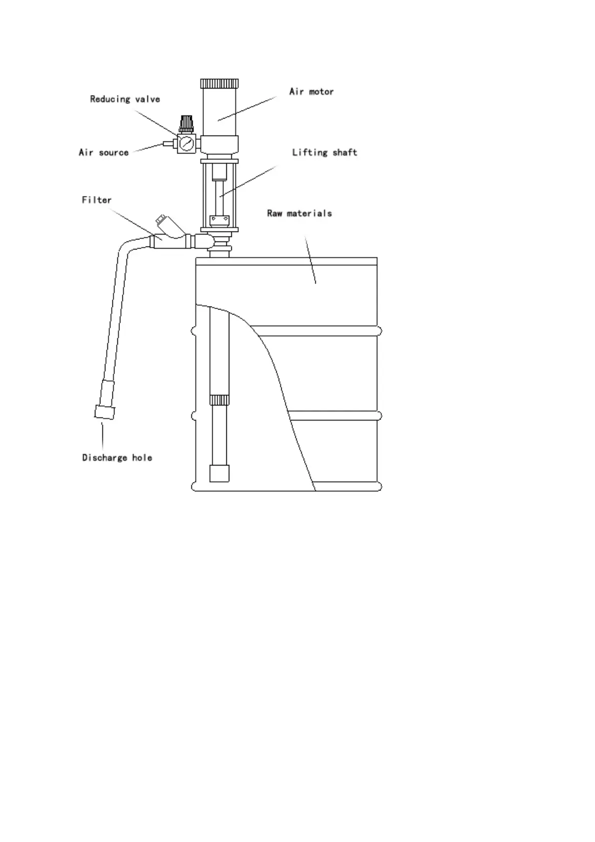
Figure 2
Step 2 , connect the feed pump conveying hose to the discharge hole filtered by the feed pump and the
inlet of pump body of the host respectively. See Figure 3.
(2) Installation of the discharging system:
Firstly, remove the plastic insulation sleeve that outside of the temperature sensor wholly, feed the
temperature sensor (armored extra-long thermocouple) at the exit of the main machine exit slowly into the
black material pipe through the black material joint of the heat preservation hose group (the hose end is
protruding). Attention shall be needed to avoid hard bending of the sensor sleeve and care shall be paid to
protect the sensor on the tip. Then, the feed material is delivered out of the heat preservation hose set in
sequence and is sent to the sprinkler gun via the main machine. This step is very easy. The hose run shall be
clearly identified to avoid incorrect connection. When the connection from the main machine to the
polyurethane sprinkler gun feed hose set is completed, it should look like Figure. 3.
(3) If it is necessary to lengthen the hose because of the construction condition, then the hose shall be
connected according to Figure(4) and the output voltage of the transformer for hose heating needs to be
adjusted to increase the heating power and satisfy the power requirement. The output voltage shall be
compatible with the pipe run length. For adjustment, observe “connect point for pipe extension” label on
the equipment and choose the voltage and connection location from Table 1 below.
Note: The factory standard configuration of this equipment is the 15m heat tracing pipe and insulation pipe,
the output voltage of the transformer for the insulation pipe is 12V.
 Loading...