Do you have a question about the JingYan TLL90S and is the answer not in the manual?
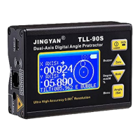
Details high accuracy up to ±0.005° and resolution of 0.001°.
Supports dual and single axis measurement with auto-rotating LCD.
Includes a laser module for level alignment purposes.
Device features a rechargeable battery for convenience.
Case design aids fitting on corners or pipes.
Features two side magnetic bases with milled surfaces.
Provides audible alarming at settable angle ranges.
Supports any angle measurement using gyro technology.
Offers USB/Bluetooth connection to PC (adapter may be required).
Supports PLC Modbus RS485 connection for networking up to 255 units.
Details potential hazards of laser products and prohibits staring into the beam.
Controls power and laser; long press to turn off.
Sets current reading to zero; long press controls buzzer.
Freezes readings; long press cycles measurement modes.
Icons indicating battery level: empty, half, and full.
Shows tilt direction graphically in dual-axis mode.
Icons for Degree, mm/M, and Gradient % modes, showing HOLD status.
Guide for charging via adapter/computer and important notes on charging status.
Explains relative and absolute modes and their icons.
Procedure for switching between relative and absolute measurement modes.
How to activate/cancel the holding function to freeze readings.
Procedure to enter the menu mode for settings.
Configures auto power off: never sleep or 30 min.
Steps to reset the unit to factory default settings.
Guides on setting alarming angles for axes and range.
Initial steps for dual axis calibration on a flat table.
Method to measure angles between any two faces using gyro technology.
Steps for calibrating the gyro sensor for accurate measurements.
Choosing between USB and RS485 for communication.
Pinouts and interface specifications for RS485 and USB ports.
Details ASCII format for data transmission in AUTO mode.
Explains RTU Modbus format for REPLY mode communication.
Table listing addresses and purposes for reading device registers.
Table detailing addresses and purposes for writing to device registers.
Procedure to choose between USB and RS485 for output.
Instructions to set transmission mode to AUTO or REPLY.
Procedure to set the Modbus device address.
Steps to select and confirm the communication baud rate.
| Brand | JingYan |
|---|---|
| Model | TLL90S |
| Category | Measuring Instruments |
| Language | English |