3) The input sensitivity of the two amplifiers
needs to be adjusted independently. To
properly calibrate the amplifiers for
maximum, identical, clean output, please
refer to Appendix A (page 14). After using this
procedure, you can then adjust the level of the
amplifiers by adjusting the input sensitivities
downward, if the amplifiers require attenuation
to achieve the desired system balance. If the
input sensitivities are adjusted, the amplifiers
must be recalibrated to ensure identical power
output levels.
Note: The “Input Range” switch on all “Slave”
amplifiers needs to be set to “Low”, even if
the “Master” amplifier is high voltage and its
switch is set to “High”. All signals passed out
of the preamp outputs of the amplifier are
compatible with the “Low” setting on the “Input
Range” control.
4) If you would like to run a third amplifier
in “Slave” configuration, select the “Full-
Range” position on the “Output Mode”
switch of the first “Slave” amplifier. Then,
connect an RCA cable from the first
“Slave” amplifier’s preamp outputs to the
second “Slave” amplifier. As you did with
the first “Slave” amplifier, set the second
“Slave” amplifier’s “Amp LP Filter” to the
“Off” position. Then, calibrate the third
amplifier’s “Input Range” and “Input
Sens.” controls in the same manner as you
did for the second amplifier.
Additional amplifiers may be added to this
“Master/Slave” configuration following the same
procedure as in step 4.
Once you match the input sensitivities of
all the amplifiers, you can use the “Master”
amplifier’s “Amp LP Filter” and “Advanced
Bass Control” features to control the “Slave”
amplifier(s). If the remote bass control (RBC-1) is
used, it need only be connected to the “Master”
amplifier to control all the amplifiers in the
“Master/Slave” chain.
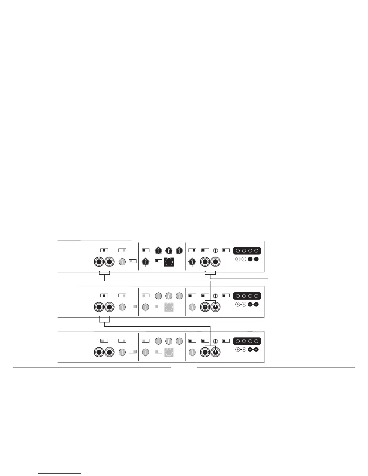
Reference the diagram showing a “Master/
Slave” configuration with one “Master” (top
amplifier) and two “Slave” amplifiers. Switches
and controls that are defeated in the “Slave”
amplifiers are printed in gray.
APPENDIX D:
Master/Slave Configurations
With the flexible on-board crossovers and
processing incorporated into the 1000/1v2, it
is possible to connect multiple 1000/1v2’s in a
“Master/Slave” configuration, with each amplifier
driving its own speaker system but controlled by
the processing and filtering of only one amplifier.
This is very useful when driving multiple
subwoofers with multiple amplifiers.
To create a Master/Slave configuration, first
determine which amplifier will be the “Master”
amplifier and connect the main input signal to
that amplifier (from the source unit or from an
outboard processor). This amplifier’s “Amp LP
Filter” section and “Advanced Bass Control”
features will process the signal for the “Slave”
amplifier or amplifiers.
Here is the procedure for implementing a
“Master/Slave” configuration:
1) Set the “Master” amplifier’s “Output Mode”
switch to the center “Amp Filter” position.
This will send a parallel, mono-summed signal
from the “Master” amplifier’s “Amp LP Filter”
section to its preamp outputs.
2) Connect an RCA cable from the “Master”
amplifier’s preamp outputs to the main input
of the first “Slave” amplifier. Set the “Slave”
amplifier’s “Amp LP Filter” to the “Off”
position. This will defeat the LP filter and the
bass processing of this “Slave” amplifier.
MASTER:
+12VDC Ground Remote Preamp Output Section Infrasonic Filter “Q” Center Freq. Boost (dB) Amp LP Filter
Advanced
Bass
Control
Ampl ifier Input Section Subwoofer Output
MONO OUTPUT ONLY
Left Output Right Output Left Ch. Right Ch.Filter Freq. (Hz) Filter Freq. (Hz)Infrasonic Freq. (Hz) Remote Bass Port
Full Range
|
Amp Filter
|
Out Filter
Output Mode Filter Slope Mode Mode
|
Slope Input Voltage Input Sens.
Outp ut Polar ity
12dB
|
24dB
Filter Mode
LP
|
HP
Bass EQ
Off
|
On
Off
|
12dB
|
24dB Low
|
High
Norm al
|
Reve rsed
Off
|
On
40
45
55
65
85
120
200 15
18
25
30
40
50
60 40
45
55
65
80
100
200
0.5
0.7
1.1
1.6
2.7
4.3
20
25
35
45
55
70
80 0
+4
+10
+13
+15
1000 /1v2
Monoblock Subwoofer Amplifier
+12VDC Ground Preamp Output Section Infrasonic Filter “Q” Center Freq. Boost (dB) Amp LP Filter
Advanced
Bass
Control
Ampl ifier Input Section Subwoofer Output
MONO OUTPUT ONLY
Left Output Right Output Left Ch. Right Ch.Filter Freq. (Hz) Filter Freq. (Hz)Infrasonic Freq. (Hz) Remote Bass Port
Full Range
|
Amp Filter
|
Out Filter
Output Mode Filter Slope Mode Mode
|
Slope Input Voltage Input Sens.
Outp ut Polar ity
12dB
|
24dB
Filter Mode
LP
|
HP
Bass EQ
Off | On
Off
|
12dB
|
24dB Low
|
High
Norm al
|
Reve rsed
Off
|
On
40
45
55
65
85
120
200 15
18
25
30
40
50
60 40
45
55
65
80
100
200
0.5
0.7
1.1
1.6
2.7
4.3
20
25
35
45
55
70
80 0
+4
+10
+13
+15
1000 /1v2
Monoblock Subwoofer Amplifier
Remote
Set all amps in chain to "Normal" OR
Set all amps in chain to "Reversed"
!
IMPORTANT
+12VDC Ground Remote Preamp Output Section Infrasonic Filter “Q” Center Freq. Boost (dB) Amp LP Filter
Advanced
Bass
Control
Ampl ifier Input Section Subwoofer Output
MONO OUTPUT ONLY
Left Output Right Output Left Ch. Right Ch.Filter Freq. (Hz) Filter Freq. (Hz)Infrasonic Freq. (Hz) Remote Bass Port
Full Range
|
Amp Filter
|
Out Filter
Output Mode Filter Slope Mode Mode
|
Slope Input Voltage Input Sens.
Outp ut Polar ity
12dB
|
24dB
Filter Mode
LP
|
HP
Bass EQ
Off | On
Off
|
12dB
|
24dB Low
|
High
Norm al
|
Reve rsed
Off
|
On
40
45
55
65
85
120
200 15
18
25
30
40
50
60 40
45
55
65
80
100
200
0.5
0.7
1.1
1.6
2.7
4.3
20
25
35
45
55
70
80 0
+4
+10
+13
+15
1000 /1v2
Monoblock Subwoofer Amplifier
Connect Master 1000/1 Preamp Output to Slave A 1000/1 Input
Connect Slave A 1000/1 Preamp Output to Slave B 1000/1 Input
Connect Master 1000/1 Input to Signal Source
Ma ke sure tha t th e "O utp ut Po lari ty"
sw itch es a re i n th e sa me posi tion for
al l th e am pli ers in a m aster/ slav e ch ain.
 Loading...