134
DISASSEMBLY
Dana Holding Corporation ASM-0025E - 212 Axle Service Manual
DISASSEMBLY
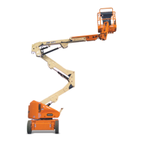
FIGURE 1: Remove the whole differential unit (2) from the
central axle unit (1).
For details, see DIFFERENTIAL UNIT p. 61.
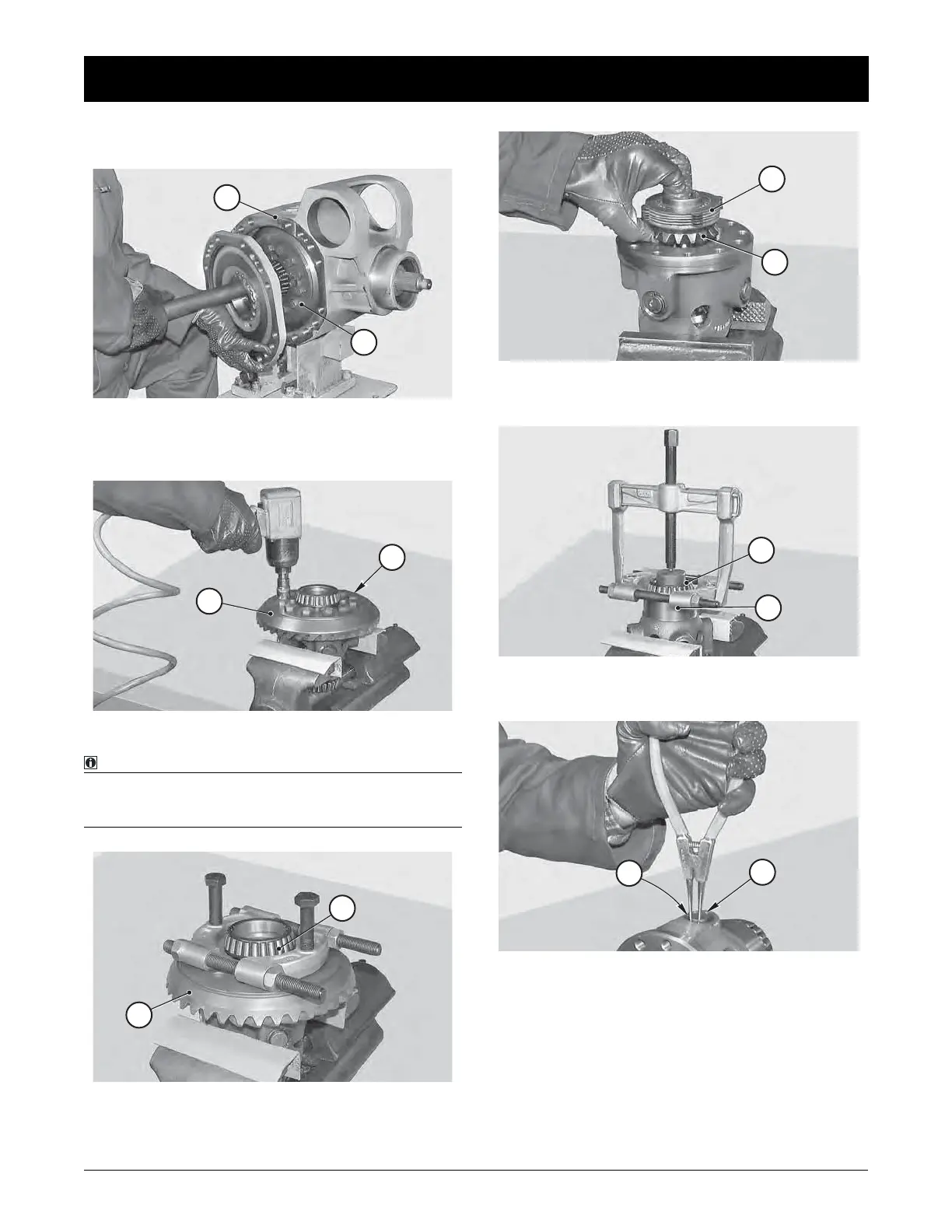
FIGURE 2: Remove the check screws (3) of the crown (4).
NOTE:
Write down the position of the notches of the central hole
in relation to the protrusions of the friction unit steel di-
scs.
FIGURE 3: If bearing (5) needs replacing, remove it; remove
crown (4).
1
2
4
3
5
4
FIGURE 4: Remove the planetary gear (6) and the whole fric-
tion unit (7).
FIGURE 5: If bearing (8) needs replacing, extract it from the
differential unit (9).
FIGURE 6: Remove the snap rings (10) from the pins (11) of
the planetary gears (12).
6
7
8
9
11
10
 Loading...