ASSEMBLY
95Dana Holding CorporationASM-0025E - 212 Axle Service Manual
ASSEMBLY
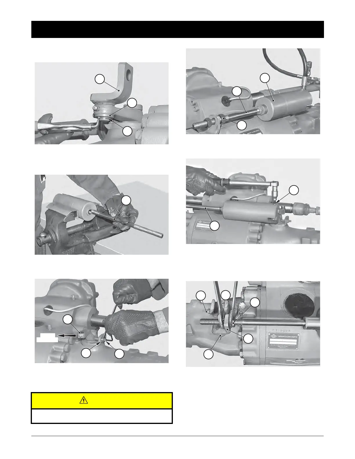
FIGURE 6: Install spacer (2) and insert the pin of support (8)
into the right-hand braking lever. Fit the second spacer (2)
and snap ring (1).
FIGURE 7: Apply Loctite 270 to the rod (5) and screw it in the
piston (13) as far as it will go.
FIGURE 8: Loosen nuts (17) and set braking levers (19) clea-
rances to zero by turning studs (18); lock nuts (17) with a tor-
que wrench setting of 20 - 25 N·m.
Clearances should be set to zero without causing any pre-
loading.
1
2
8
5
19
18
17
CAUTION
FIGURE 9: Install cylinder (4) complete with rod (5) and inter-
nal nut (6).
FIGURE 10: Center the hole of fulcrum pin (3) and washers
(12).
Apply Loctite 242 to the pin thread, screw and tighten pin
with a torque wrench set at 25 - 30 N·m.
FIGURE 11: Introduce pressure into the cylinder (4) and while
holding both levers (19) back against the adjusting screws
(18), move nuts (6) and (7) so that they are made to rest
against support (8); lock the nuts with a torque wrench setting
of 50 - 60 N·m.
4
6
5
5
3
6
7
8
19
18



 To Next Page