32
5.3.2.1-1
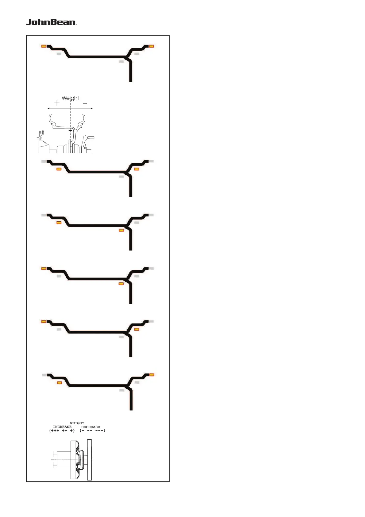
5.3.2.2-1
5.3.2.2-3
5.3.2.2-4
5.3.2.2-6
5.3.2.2-5
5.3.2.2-2
5.3.2.1-2
Operation
5.3.2 Balancing
This chapter describes how to balance a wheel.
For help on:
rim data input refer to Chapter 5.3.1
spinning the wheel refer to Chapter 5.3.3
weight application refer to Chapter 5.3.4
the check spin refer to Chapter 5.3.5
5.3.2.1 Normal weight mode
When selected, the display is as shown in Figure 5.3.2.1-
1.
Figure 5.3.2.1-2 shows the rim reference point.
• Establish the following dimensions:
- Rim diameter of the reference point.
- Rim width.
- Offset of the reference point.
• After entering the dimensions, spin the wheel.
• Apply the clip-on weights at the indicated positions,
at the 12 o’clock position.
• Perform a check spin when done.
5.3.2.2 ALU weight modes
Select an ALU weight mode if one or more stick-on
weights will be used.
When selected, the display shows:
ALU1: Refer to Figure 5.3.2.2-1.
ALU2: Refer to Figure 5.3.2.2-2.
ALU3: Refer to Figure 5.3.2.2-3.
ALU4: Refer to Figure 5.3.2.2-4.
ALU5: Refer to Figure 5.3.2.2-5.
• Establish the following dimensions:
- Rim diameter of the reference point.
- Rim width.
- Offset of the reference point.
Note: For ALU2 and ALU3 the right hand plane
is equal to the front surface of the ! ange.
The weight should be applied in that
plane. Deviations in that plane should be
compensated by increasing or reducing
the weight applied. Refer to Figure 5.3.2.2-
6.
• After entering the dimensions
, spin the wheel.
• Apply the clip-on/stick-on weights at the indicated
12 o’clock positions.
• Perform a check spin when done.
.