96
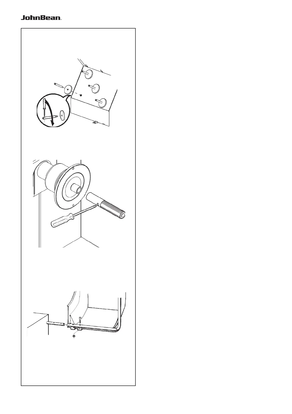
iii-1
iii-2
iii-3
Installation Instructions
iii Installation procedures
Wheel balancer:
Refer to the drawing in i for correct wheel balancer
positioning. If the wheel balancer needs securing,
we recommend fi xing elements with a diameter of
8 mm, quality 8.8 or higher.
Supports for Accessories:
• Unpack the 4 threaded accessory support studs
and the support plates.
• Refer to Figure iii-1. Fit the 4 threaded accessory
support studs and the plates.
Stub shaft:
• Clean the stub shaft and the hole in the main shaft.
• Refer to Figure iii-2. Position the stub shaft.
• Use a pin (Ø max.10mm) to tighten.
Wheel guard:
• Refer to Figure iii-3. Fix the wheel guard on the
shaft which sticks out at the back on the right.
Clamping devices:
• Put the clamping devices on the accessory studs.
.